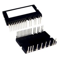
FNB41060 Fairchild Semiconductor, FNB41060 Datasheet - Page 7

FNB41060
Manufacturer Part Number
FNB41060
Description
MOD SPM 600V 10A SPM26-AA
Manufacturer
Fairchild Semiconductor
Series
SPM™r
Type
IGBTr
Datasheet
1.FNB41060.pdf
(16 pages)
Specifications of FNB41060
Configuration
3 Phase Inverter
Current
10A
Voltage
600V
Voltage - Isolation
2000Vrms
Package / Case
SPM26-AA
Product
IGBT Silicon Modules
Collector- Emitter Voltage Vceo Max
600 V
Collector-emitter Saturation Voltage
1.5 V
Power Dissipation
32 W
Maximum Operating Temperature
+ 150 C
Minimum Operating Temperature
- 40 C
Mounting Style
Through Hole
Lead Free Status / RoHS Status
Lead free / RoHS Compliant
Available stocks
Company
Part Number
Manufacturer
Quantity
Price
Company:
Part Number:
FNB41060
Manufacturer:
INNEL
Quantity:
560
Part Number:
FNB41060
Manufacturer:
FAIRCHILD/ن»™ç«¥
Quantity:
20 000
Company:
Part Number:
FNB41060B2
Manufacturer:
SEMIKRON
Quantity:
5
FNB41060/B2 Rev. C
Switching Loss (Typical)
Control Part
Note:
5. Short-circuit current protection is functioning only at the low-sides.
6. T
Symbol
V
V
V
UV
UV
UV
UV
I
TH
I
I
I
V
V
IN(OFF)
QCCH
QCCL
PCCH
I
SC(ref)
t
PCCL
I
IN(ON)
R
QBS
FOD
PBS
FOH
FOL
is the temperature of thermister itselt. To know case temperature (T
CCD
CCR
TH
BSD
BSR
400
350
300
250
200
150
100
50
0
0
Quiescent V
Current
Operating V
Current
Quiescent V
Current
Operating V
Current
Fault Output Voltage
Short Circuit Trip Level V
Supply Circuit
Under-Voltage
Protection
Fault-out Pulse Width
ON Threshold Voltage
OFF Threshold Voltage
Resistance of
Thermister
Inductive Load, V
Parameter
IGBT Turn-ON, E
IGBT Turn-OFF, E
FRD Turn-OFF, E
1
COLLECTOR CURRENT, I
CC
BS
CC
BS
Supply
Supply
Supply
Supply
2
PN
on
=300V, V
rec
off
V
V
V
duty=50%, applied to one PWM
signal input for High-side
V
duty=50%, applied to one PWM
signal input for Low-side
V
V
duty=50%, applied to one PWM
signal input for High-side
V
V
Detection Level
Reset Level
Detection Level
Reset Level
Applied between IN
IN
@T
@T
3
Figure 5. Switching Loss Characteristics
CC(H)
CC(L)
CC(H)
CC(L)
BS
CC
SC
SC
CC
(WL)
TH
TH
c
= 15V, IN
= 0V, V
= 1V, V
= 15V (Note 5)
[AMPERES]
= V
CC
=25°C, (Note 6)
=100°C
= 15V, IN
- COM
=15V, T
= 15V, IN
= 15V, f
= 15V, f
BS
4
FO
FO
= 15V, f
(UH, VH, WH)
J
Circuit: 4.7kW to 5V Pull-up
Circuit: 4.7kW to 5V Pull-up
=25
(UH,VH,WH)
(UL,VL, WL)
C
PWM
PWM
), please make the experiment considering your application.
5
℃
PWM
(UH)
Conditions
= 20kHz,
= 20kHz,
, IN
= 20kHz,
= 0V
= 0V
= 0V
7
(VH)
, IN
400
350
300
250
200
150
100
50
0
V
V
V
V
V
V
V
V
(WH)
0
CC(H)
CC(L)
CC(H)
CC(L)
B(U)
S(V)
B(U)
S(V)
Inductive Load, V
, IN
, V
, V
- V
- V
- COM
- COM
- COM
- COM
B(W)
B(W)
(UL)
S(U)
S(U)
IGBT Turn-ON, E
IGBT Turn-OFF, E
FRD Turn-OFF, E
1
COLLECTOR CURRENT, I
, IN
, V
, V
- V
- V
B(V)
B(V)
S(W)
S(W)
(VL)
-
-
,
2
PN
Min.
0.45
10.5
11.0
10.0
10.5
=300V, V
4.5
0.8
30
on
-
-
-
-
-
-
-
-
-
-
rec
off
3
Typ.
CC
c
0.5
2.9
47
[AMPERES]
-
-
-
-
-
-
-
-
-
-
-
-
-
-
-
=15V, T
4
Max. Units
0.10
2.65
0.15
3.65
0.30
2.00
0.55
13.0
13.5
12.5
13.0
0.5
2.6
J
www.fairchildsemi.com
=150
-
-
-
-
-
℃
5
mA
mA
mA
mA
mA
mA
kW
kW
ms
V
V
V
V
V
V
V
V
V


