FSAB20PH60 Fairchild Semiconductor, FSAB20PH60 Datasheet
FSAB20PH60
Specifications of FSAB20PH60
Available stocks


Related parts for FSAB20PH60


FSAB20PH60 Summary of contents
Page 1
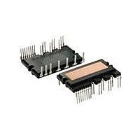
... Fairchild Semiconductor Corporation FSAB20PH60 Rev. A General Description FSAB20PH60 is an advanced smart power module of PSC(Par- tial Switching Converter) that Fairchild has newly developed and designed mainly targeting low-power application especially for an air conditioners. It combines optimized circuit protection and drive IC matched to IGBTs. System reliability is further enhanced by the integrated under-voltage lock-out and short- circuit protection function ...
Page 2
... NC (11) NC (11) NC (12) NC (12) NC (13) NC (13) NC (14) NC (14) NC (15) NC (15) NC (16) NC (16) NC (17) NC (17) NC (18) NC (18) NC (19) R (19 (20) V (20 FSAB20PH60 Rev. A Top View Top View (21) N (21) N (22) N (22) N (23) N (23) N (24) NC (24) NC (25) R (25) R (26) S (26) S (27) P (27) P Figure ...
Page 3
... The low-side is composed of two IGBTs including rectifying diodes for each IGBT and one control IC which has gate driving, current sensing and protection functions. The high- side is composed of two rectifying diodes without gate driving IC. FSAB20PH60 Rev. A Pin Description Common Bias Voltage for IC ...
Page 4
... Current Sensing Input Voltage Applied between C SC Total System Symbol Parameter T Module Case Operation Temperature C T Storage Temperature STG V Isolation Voltage ISO FSAB20PH60 Rev 25°C, Unless Otherwise Specified) J Conditions Applied between R-S Applied between R-S Applied between P-N Applied between P-N IGBT Diode ≤ 90° 280V, f ...
Page 5
... IC OFF For the detailed information, please see Figure 4. 100 10% I IN(ON) FSAB20PH60 Rev. A Conditions Each IGBT under Operating Condition Each Diode under Operating Condition ), please refer to Figure 25°C, Unless Otherwise Specified) J Conditions =15V I = 6.5A, T ...
Page 6
... V Output Voltage PN V Control Supply Voltage CC f PWM Input Signal PWM Note: 6. Regarding the switching method of FSAB20PH60, it follows the control method of the typical partial-switching power factor correction circuit as shown in Figure 5. FSAB20PH60 Rev 25°C, Unless Otherwise Specified) J Conditions V = 15V V - COM CC CC(L) ...
Page 7
... Each IGBT turns on with zero current with the utility frequency 60Hz. FSAB20PH60 Rev Input Current IGBT Current 10 0 -10 - Diode Current -10 - turned on at the zero crossing point of input voltage, and turned off considering the output power and distortion of input 1 2 Figure 5. PWM Example of FSAB20PH60 ...
Page 8
... Mechanical Characteristics and Ratings Parameter Mounting Torque Mounting Screw: M3 Heatsink Flatness Weight FSAB20PH60 Rev. A Conditions Recommended 0.62Nm Note Fig. 6 (+) (+) Figure 6. Flatness Measurement Position 8 Limits Units Min. Typ. Max. 0.51 0.62 0.72 N• 120 um - 15. (+) www.fairchildsemi.com ...
Page 9
... Control supply voltage rises: After the voltage rises Normal operation: IGBT ON and carrying current Under voltage detection (UV CCD a4 : IGBT OFF in spite of control input condition Fault output operation starts Under voltage reset (UV ). CCR a7 : Normal operation: IGBT ON and carrying current. FSAB20PH60 Rev. A RESET SET UV CCR a1 UV CCD a3 a2 ...
Page 10
... Fault output timer operation starts: The pulse width of the fault output signal is set by the external capacitor Input “L” : IGBT OFF state Input “H”: IGBT ON state, but during the active period of fault output the IGBT doesn’t turn ON IGBT OFF state FSAB20PH60 Rev SET RESET ...
Page 11
... The logic input is compatible with standard CMOS or LSTTL outputs. Figure 9. Recommended CPU I/O Interface Circuit 120 100 Figure 10. R-T Curve of the Built-in Thermistor FSAB20PH60 Rev. A 5V-Line Ω 4.7k Ω 100 1nF 1nF R-T Graph 100 110 120 130 Temperature [° ...
Page 12
... When selecting protecting current level, please consider the variation and tolerance of external components. Moreover, the shunt resistor path from SH N and and ground that is connected to COM of the internal drive IC, should be thick and short in order to minimize the stray inductance that may generate improper switching of the module. FSAB20PH60 Rev. A +5V PSC Module, FSAB20PH60 V TH NTC R TH Thermistor CSC C ...
Page 13
... Detailed Package Outline Drawings FSAB20PH60 Rev www.fairchildsemi.com ...
Page 14
... Detailed Package Outline Drawings FSAB20PH60 Rev. A (Continued) 14 www.fairchildsemi.com ...
Page 15
... Detailed Package Outline Drawings FSAB20PH60 Rev. A (Continued) 15 www.fairchildsemi.com ...
Page 16
... PRODUCT STATUS DEFINITIONS Definition of Terms Datasheet Identification Advance Information Preliminary No Identification Needed Obsolete FSAB20PH60 Rev. A IntelliMAX™ POP™ ISOPLANAR™ Power247™ LittleFET™ PowerEdge™ MICROCOUPLER™ PowerSaver™ MicroFET™ ...