P123 Vishay, P123 Datasheet - Page 6
P123
Manufacturer Part Number
P123
Description
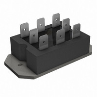
SCR HY-BRIDGE 800V 25A PACE-PAK
Manufacturer
Vishay
Specifications of P123
Mounting Type
Chassis Mount
Package / Case
6-PACE-PAK
Structure
Bridge, Single Phase - SCRs/Diodes (Layout 3)
Number Of Scrs, Diodes
2 SCRs, 2 Diodes
Voltage - Off State
800V
Current - Gate Trigger (igt) (max)
60mA
Current - On State (it (rms)) (max)
25A (DC)
Current - Non Rep. Surge 50, 60hz (itsm)
357A, 375A
Current - Hold (ih) (max)
130mA
Peak Reflow Compatible (260 C)
Yes
Current Rating
25A
Forward Voltage
1.35V
Lead Free Status / RoHS Status
Lead free / RoHS Compliant
Current - On State (it (av)) (max)
-
Lead Free Status / RoHS Status
Lead free / RoHS Compliant, Lead free / RoHS Compliant
Other names
*P123
VS-P123
VS-P123
VSP123
VSP123
VS-P123
VS-P123
VSP123
VSP123
Available stocks
Company
Part Number
Manufacturer
Quantity
Price

Part Number:
P123
Manufacturer:
POLYFET
Quantity:
20 000
Part Number:
P12304-01AT
Manufacturer:
HAMAMATSU
Quantity:
20 000
Part Number:
P12305
Manufacturer:
SC
Quantity:
20 000


P100 Series
Bulletin I27125 rev. A 04/99
6
Fig. 6 - Maximum Non-Repetitive Surge Current
Number Of Equal Amplitude Half Cycle Current Pulses (N)
350
300
250
200
150
1
P100 Series
Per Junction
0.01
100
0.1
0.1
10
10
0.0001
At Any Rated Load Condition And With
0.001
1
1
Rated V
Rectangular gate pulse
a)Recommended load line for
b)Recommended load line for
VGD
rated di/dt : 10 V, 65 ohms, tr <= 1µs
rated di/dt : 10V, 20 ohms, tr <= 1µs
Steady State Value:
R
(DC Operation)
RRM
thJC
IGD
Applied Following Surge.
10
= 2.24K/W
0.001
0.01
Fig. 8 - Thermal Impedance Z
Initial T = 125°C
@ 60 Hz 0.0083 s
@ 50 Hz 0.0100 s
J
Square Wave Pulse Duration (s)
Instantaneous Gate Current (A)
Fig. 9 - Gate Characteristics
(b)
0.01
100
0.1
(a)
P100 Series
thJC
0.1
1
Characteristics
Fig. 7 - Maximum Non-Repetitive Surge Current
(1) PGM = 100 W, tp = 500 µs
(2) PGM = 50 W, tp = 1 ms
(3) PGM = 20 W, tp = 25 ms
(4) PGM = 10 W, tp = 5 ms
400
350
300
250
200
150
100
P100 Series
Per Junction
0.01
Frequency Limited
By PG(AV)
(4)
P100 Series
Per Junction
Of Conduction May Not Be Maintained.
Maximum Non Repetitive Surge Current
10
1
(3)
Versus Pulse Train Duration. Control
Pulse Train Duration (s)
(2)
Rated V
(1)
No Voltage Reapplied
0.1
100
10
Initial T = 125°C
RRM
www.irf.com
Reapplied
J
1
Related parts for P123
Image
Part Number
Description
Manufacturer
Datasheet
Request
R

Part Number:
Description:
357-036-542-201 CARDEDGE 36POS DL .156 BLK LOPRO
Manufacturer:
Vishay
Datasheet:
Part Number:
Description:
357-036-542-201 CARDEDGE 36POS DL .156 BLK LOPRO
Manufacturer:
Vishay
Datasheet:
Part Number:
Description:
357-036-542-201 CARDEDGE 36POS DL .156 BLK LOPRO
Manufacturer:
Vishay
Datasheet:
Part Number:
Description:
357-036-542-201 CARDEDGE 36POS DL .156 BLK LOPRO
Manufacturer:
Vishay
Datasheet:
Part Number:
Description:
357-036-542-201 CARDEDGE 36POS DL .156 BLK LOPRO
Manufacturer:
Vishay
Datasheet:
Part Number:
Description:
357-036-542-201 CARDEDGE 36POS DL .156 BLK LOPRO
Manufacturer:
Vishay
Datasheet:
Part Number:
Description:
357-036-542-201 CARDEDGE 36POS DL .156 BLK LOPRO
Manufacturer:
Vishay
Datasheet:
Part Number:
Description:
357-036-542-201 CARDEDGE 36POS DL .156 BLK LOPRO
Manufacturer:
Vishay
Datasheet:
Part Number:
Description:
357-036-542-201 CARDEDGE 36POS DL .156 BLK LOPRO
Manufacturer:
Vishay
Datasheet:
Part Number:
Description:
357-036-542-201 CARDEDGE 36POS DL .156 BLK LOPRO
Manufacturer:
Vishay
Datasheet:
Part Number:
Description:
357-036-542-201 CARDEDGE 36POS DL .156 BLK LOPRO
Manufacturer:
Vishay
Datasheet:
Part Number:
Description:
357-036-542-201 CARDEDGE 36POS DL .156 BLK LOPRO
Manufacturer:
Vishay
Datasheet:
Part Number:
Description:
357-036-542-201 CARDEDGE 36POS DL .156 BLK LOPRO
Manufacturer:
Vishay
Datasheet:
Part Number:
Description:
357-036-542-201 CARDEDGE 36POS DL .156 BLK LOPRO
Manufacturer:
Vishay
Datasheet:
Part Number:
Description:
357-036-542-201 CARDEDGE 36POS DL .156 BLK LOPRO
Manufacturer:
Vishay
Datasheet: