EE-SX672 Omron, EE-SX672 Datasheet - Page 8
EE-SX672
Manufacturer Part Number
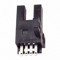
EE-SX672
Description
OPTO SENSOR 5MM SLOTTYPE T-SHAPE
Manufacturer
Omron
Specifications of EE-SX672
Sensing Distance
0.197" (5mm)
Sensing Method
Transmissive
Output Configuration
NPN - Dark-ON/Light-ON - Selectable
Mounting Type
Chassis Mount
Current - Supply
35mA
Voltage - Supply
5 V ~ 24 V
Package / Case
Module, Connector
No. Of Pins
4
Opto Case Style
Slotted
No. Of Channels
1
Operating Temperature Range
-25°C To +55°C
Operating Voltage Max
24VDC
Operating Voltage Min
5VDC
Svhc
No SVHC (15-Dec-2010)
Frequency Response Max
1kHz
Sensing Range Max
5mm
Sensor Input
Optical
Supply Voltage Dc Max
24VDC
Connector Type
DEDICATED 1 OR 2
External Depth
26mm
Output Type
Light - On / Off
Slot Width
5mm
External Length / Height
22.2mm
Input Current
35mA
Input Current Max
35mA
Rohs Compliant
Yes
Lead Free Status / RoHS Status
Lead free / RoHS Compliant
Response Time
-
Lead Free Status / Rohs Status
Lead free / RoHS Compliant
Other names
EESX672
OR530
OR530
Available stocks
Company
Part Number
Manufacturer
Quantity
Price
Company:

Part Number:
EE-SX672
Manufacturer:
OMRON
Quantity:
1 000
Part Number:
EE-SX672
Manufacturer:
OMRON/欧姆龙
Quantity:
20 000
Company:
Part Number:
EE-SX672-WR 1M
Manufacturer:
Omron Industrial
Quantity:
135
Company:
Part Number:
EE-SX672A
Manufacturer:
Omron Electronics
Quantity:
135
Part Number:
EE-SX672A
Manufacturer:
OMRON进口
Quantity:
20 000


EE-SX67/47
Precautions
Do not use the EE-SX at voltage exceeding the rated voltage range,
otherwise the EE-SX may be damaged.
Do not make mistakes in wiring, such as mistakes in polarity, other-
wise the EE-SX may be damaged.
Do not short-circuit the load (i.e., do not connect a power supply di-
rectly to the Sensor) as shown below, otherwise the EE-SX may be
damaged.
Mounting
The EE-SX is a Sensor to be built into equipment. Therefore, no
special protective measures have been taken to protect the EE-SX
from external light disturbance. Make sure that the EE-SX is not
affected by incandescent lamps or other light sources that may
cause external light disturbance, otherwise the EE-SX may mal-
function.
Be sure to mount the Sensor securely to flat plates. The characteris-
tics of the Through-beam Sensor change if the slot is deformed.
Use M3.0 screws when mounting the EE-SX. Be sure to use spring
washers with the screws so that the screws will not loosen. The
tightening torque applied to each screw must be no more than
0.59 N m (6 kgf cm).
Make sure that nothing will come into contact with the sensing ele-
ment of the Sensor. If the sensing element has scratch damage, the
characteristics of the Sensor will decrease.
Make sure that the EE-SX is securely mounted and not loosened by
vibration or shock.
Wiring
Countermeasures Against Surge
If the power supply has surge voltage, connect a Zener diode with-
standing 30 to 35 V or 0.1 to 1- F capacitor in parallel to the power
supply to absorb the surge voltage.
8
!
Caution
Sensor
Sensor
Sensor
+
Out
–
+
Out
+
Out
–
–
Load
Load
Load
Load
short-circuiting
0.1 to 1 F
If the load is a relay or other small inductive load, connect the load to
the EE-SX as shown below. Be sure to connect a diode for counter-
voltage absorption.
Do not wire power lines or high-tension lines alongside the lines of
the EE-SX in the same conduit, otherwise the EE-SX may be dam-
aged or malfunction due to induction. Be sure to wire the lines of the
EE-SX separately from power lines or high-tension lines or lay them
in an exclusive, shielded conduit.
Voltage Output
A Sensor with open collector output can be connected to a device
with voltage-input specifications by connecting a resistor between
the power supply and output terminals as shown in the following cir-
cuit diagram. The resistance of the resistor is normally 4.7 k and
must withstand a power of 0.5 W at 24 V and 0.25 W at 12 V.
EE-SX47/67 NPN Models with a 4.7-k Resistor
High level:
Low level:
EE-SX47/67 PNP Models with a 4.7-k Resistor
High level:
Low level:
Note: Refer to the ratings of the Sensor for the relationship be-
Input voltage (V
Input voltage (V
Input voltage (V
Load current (I
EE-SX67/47 NPN models
Sensor
main
circuit
EE-SX67/47 PNP models
tween the residual voltage and load current.
Sensor
main
circuit
Input voltage (V
C
H
L
L
) =
)
) =
) x 0.4 V
0 V
V
CC
R+Z
R
OUT
Output
Z
Output
H
=
)
V
Resistor
CC
24 V
= Vcc–residual voltage
Resistor
R
24 V–1.3 V=22.7 V
=
4.7 k + 4.7 k
Relay
Counter (voltage-input model)
= 5.1 mA x 50 to 100 mA
Input terminal (CP)
+24 V (power supply)
4.7 k
Input terminal (CP)
+24 V (power supply)
Input impedance:
approx. 4.7 k
Input impedance:
approx. 4.7 k
EE-SX67/47
x 24 V = 12 V
Related parts for EE-SX672
Image
Part Number
Description
Manufacturer
Datasheet
Request
R

Part Number:
Description:
PHOTO MICROSENSOR 0.5MM DARK ON
Manufacturer:
Omron
Datasheet:

Part Number:
Description:
OPTO SENSOR 5MM LT/DARKON PNP
Manufacturer:
Omron
Datasheet:

Part Number:
Description:
OPTO SENSOR 5MM LIGHTON NPN
Manufacturer:
Omron
Datasheet:

Part Number:
Description:
OPTO SENSOR 5MM LT/DARKON PNP
Manufacturer:
Omron
Datasheet:

Part Number:
Description:
OPTO SENSOR 5MM LT/DARKON NPN
Manufacturer:
Omron
Datasheet:

Part Number:
Description:
SENSOR OPTO 5MM LIGHT-ON TRANS
Manufacturer:
Omron
Datasheet:

Part Number:
Description:
OPTO SENSOR 5MM LT/DARKON PNP
Manufacturer:
Omron
Datasheet:

Part Number:
Description:
OPTO SENSOR 13MM SLOT LIGHT-ON
Manufacturer:
Omron
Datasheet:

Part Number:
Description:
SENSOR PHOTOMICRO 5-24VDC 2M
Manufacturer:
Omron
Datasheet:

Part Number:
Description:
OPTO SENSOR 8MM WIDE SLOT TYPE
Manufacturer:
Omron
Datasheet:


Part Number:
Description:
PHOTO MICROSENSOR
Manufacturer:
Omron
Datasheet:

Part Number:
Description:
PHOTO MICROSENSOR :
Manufacturer:
Omron
Datasheet:
Part Number:
Description:
PHOTO MICROSENSOR
Manufacturer:
Omron
Datasheet:

Part Number:
Description:
PHOTO MICROSENSOR
Manufacturer:
Omron
Datasheet: