EE-SPZ401W-02 Omron, EE-SPZ401W-02 Datasheet
EE-SPZ401W-02
Specifications of EE-SPZ401W-02
Available stocks


Related parts for EE-SPZ401W-02

EE-SPZ401W-02 Summary of contents
Page 1
... Light-ON Dark-ON NPN output 5 mm Light-ON Dark- Light-ON Cable length Model EE-1002 1 m EE-1003 0.46 m (total length) EE-2001 EE-1003A For EE-1003 only. (c)Copyright OMRON Corporation 2008 All Rights Reserved. Infrared light Output Model configuration EE-SPZ301W-01 EE-SPZ401W-01 EE-SPZ301W-02 EE-SPZ401W-02 EE-SPZ301Y-01 EE-SPZ401Y-01 Remarks 1 ...
Page 2
... The response frequency was measured by detecting the following rotating disk. 200 mm dia Reflective type Through-beam type http://www.ia.omron.com/ Through-beam EE-SPZ301W-02 EE-SPZ401W- Opaque dia. min. 2 for 3 times each and Z directions Approx. 7.0 g (c)Copyright OMRON Corporation 2008 All Rights Reserved. EE-SPZ Reflective EE-SPZ301Y-01 EE-SPZ401Y- White paper (15 × 15 mm) ...
Page 3
... Releases Operates 6 5 Optical axis White paper 2 (Reflection factor: 90 −3 −2 − Optical Distance X (mm) axis http://www.ia.omron.com/ EE-SPZ301W-02, EE-SPZ401W-02 1,000 700 500 300 100 Operating level Distance d (mm) Receiver Output vs. Bending Radius EE-SPZ301Y-01, EE-SPZ401Y-01 120 110 Through-beam 100 90 80 Reflective ...
Page 4
... I/O Circuit Diagrams NPN Output Model Output configuration EE-SPZ401W-02 Light-ON EE-SPZ401Y-01 EE-SPZ301W-02 Dark-ON EE-SPZ301Y-01 http://www.ia.omron.com/ Timing charts Incident Interrupted Light indicator ON (red) OFF Output ON transistor OFF Light indicator Load 1 Operates (red) (relay) Releases H Load 2 Main L circuit Incident Interrupted ON Light indicator ...
Page 5
... Install the fiber with a holder or clip. ● Wiring • A fiber that has been once connected cannot be disconnected for reuse. • Connection is made using a Connector. Do not solder to the pin (lead). ...
Page 6
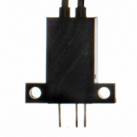
... Dimensions Unless otherwise specified, the tolerance class IT16 is used for dimensions in this data sheet. Sensors EE-SPZ301W-01 EE-SPZ401W-01 Terminal Arrangement (1) Vcc (2) OUT OUTPUT (3) GND (0 V) EE-SPZ301W-02 EE-SPZ401W-02 Terminal Arrangement (1) Vcc (2) OUT OUTPUT (3) GND (0 V) EE-SPZ301Y-01 EE-SPZ401Y-01 6.2 9.2 Terminal Arrangement (1) Vcc (2) OUT ...
Page 7
... Precautions for Safe Use To ensure safety, observe the following precautions. ●Wiring Item Power Supply DC 3-Wire NPN Output Sensors Do not apply any voltage exceed- ing the operating voltage range. Applying any excessive voltage or supplying AC power (100 VAC or higher DC-type sensor may cause the Sensor to explode or burn ...
Page 8
... W for a supply voltage and 1/4 W for 12 V. <Example> EE-SX670 SW main circuit If resistance R = 4.7 kΩ for the EE-SX670, the input voltage at the high level is as follows: Input voltage V in the D And the input voltage and load current at the low level are as follows: ...
Page 9
... Voltage drops due to the resistance of the cable material itself will also influence performance. Therefore, factors, such as the difference in voltage between the end of the cable and the sensor and noise levels, must be given full consideration VDC Capacitance OUT of 10 μ ...
Page 10
... Extension cable Precautions for Reflective Photomicrosensors <Sensing Distance> • The Reflective Photomicrosensor model is based on sensing a sheet of white paper with a reflection factor of 90%. The sensing distance varies with the other conditions of the objects being detected. <Typical Example> EE-SPY30/40 Series ...
Page 11
... Brown (Vcc) Black (OUT) CP1(N) Main CP2(N) circuit VDC (Reset) Blue (GND) Input common (c)Copyright OMRON Corporation 2008 All Rights Reserved. Operating from different power supplies Brown (Vcc) Black Main Relay circuit (OUT) Blue (GND) Transistor input (voltage input) External resistance ...
Page 12
... Be sure to use the Sensor under the rated ambient temperature. • The Sensor may be dissolved by exposure to organic solvents, acids, alkali, aromatic hydrocarbons or chloride resin hydrocarbons, causing deterioration in characteristics. Do not expose the Sensor to such chemicals. http://www.ia.omron.com/ Photomicrosensors Technical Guide (c)Copyright OMRON Corporation 2008 All Rights Reserved. C-6 ...
Page 13
... Please read and understand this catalog before purchasing the products. Please consult your OMRON representative if you have any questions or comments. WARRANTY OMRON's exclusive warranty is that the products are free from defects in materials and workmanship for a period of one year (or other period if specifi ed) from date of sale by OMRON. OMRON MAKES NO WARRANTY OR REPRESENTATION, EXPRESS OR IMPLIED, REGARDING NON-INFRINGEMENT, MERCHANTABILITY, OR FITNESS FOR PARTICULAR PURPOSE OF THE PRODUCTS ...