19252 Desco, 19252 Datasheet - Page 3
19252
Manufacturer Part Number
19252
Description
TESTER COMBO WS & FG W/STAND
Manufacturer
Desco
Type
Testerr
Specifications of 19252
Features
Base Plate and Stand
Power Supply Type
Battery (Optional AC Adapter)
Application
Test footwear or wrist straps
Circuit Type
Dual Test
Display Type
LED
Footwear Range
750 Kilohms to 100 Megohms
Standards
UL Listed
Wrist Strap Range
750 Kilohms to 10 Megohms
Description/function
Fast, frequent testing of ESD personnel grounding devices
Product
Static Monitors
For Use With/related Products
Wrist Straps, Footwear
Lead Free Status / RoHS Status
Not applicable / Not applicable
Other names
16-1084
19252
19252


TB-2040 Page 3 of 6
I.
II.
Figure 6. Installing ground cord to “FOOTPLATE” jack
III. Press the rocker switch toward “FOOTPLATE.”
IV. Place one foot on the plate. If the floor is conductive, lift the
V.
VI. Lighting of the green “PASS” LED indicates that the foot
V.
VI. Repeat steps III through VI with other foot.
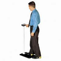
Free Standing Test Fixture Assembly and
Operation (Model 19252)
The 19252’s rugged steel pedestal tube is powder coated in a
non-conductive white finish that helps to prevent false readings if
contacted by skin or loose smocks.
Figure 8. The
Figure 7. Testing foot grounding devices with 19253.
Place the Foot Plate on the floor in front of the Combo Tester.
Plug the plate’s ground cord into the jack on the left hand
side of the unit.
NOTE: Steps I and II are not required with the 19252.
foot you are not testing off of the floor during this test. Make
sure there is no cord plugged into the “WRIST CORD” jack.
Press the test button so that the unit activates. Hold for 2-3
seconds.
ground assemblies are functioning properly.
If either red “FAIL LO” or red “FAIL HI” LEDs light and the
audible indicator sounds, the wearer should check the foot
grounding device immediately.
19252
DESCO EAST - One Colgate Way, Canton, MA 02021-1407 • (781) 821-8370 • Fax (781) 575-0172 • Website:
Free Standing Test Fixture
DESCO WEST - 3651 Walnut Avenue, Chino, CA 91710 • (909) 627-8178 • Fax (909) 627-7449
Assembly
I.
II.
Figure 9. Attaching pedestal to baseplate
III. Open the compartment and attach the snap connector to the
IV. Install the Tester on the bracket by aligning keyholes on the
Figure 10. Installing Tester on bracket and securing Tester to
bracket
V.
VI. Twist the thumb screw clockwise to secure the tester to the
WRIST STRAP TESTING
This test verifies that a continuous path between the operator,
wrist strap, and ground cord exists.
I.
II.
III. Press the test button so that the unit activates. Hold down for
NOTE: DO NOT TOUCH ANY OTHER METAL WHILE
PERFORMING TEST.
Remove 3 screws from baseplate.
Position pedestal on the baseplate with the Tester mounting
bracket pointing away from the operator. Attach pedestal to
baseplate using the three screws provided. Tighten with hex
wrench provided.
included 9 volt battery. Attach poster to the wall at eye level
in front of the Tester location.
back of tester with mounting studs on bracket. While pushing
up on thumb screw, insert the mounting studs into the
keyholes and slide the tester down. See Figure 10.
Install the 4” banana plug connector to “FOOTPLATE” jack on
the side of the unit. Insert ring terminal behind thumb screw.
bracket. Cover thumb screw with vinyl insulator cap.
While wearing the wrist strap, plug the banana plug end of
the cord into the jack on the face of the unit.
Press rocker switch toward “WRIST CORD”.
2-3 seconds.
Thumb screw
Desco.com
© 2009 DESCO INDUSTRIES INC.
Employee Owned