H-38-11 Bourns Inc., H-38-11 Datasheet - Page 38
H-38-11
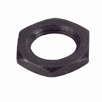
Manufacturer Part Number
H-38-11
Description
HDWR NUT MOUNTING FOR ECW ENCODR
Manufacturer
Bourns Inc.
Type
Mounting Nutr
Series
Hr
Datasheet
1.H-37-2.pdf
(73 pages)
Specifications of H-38-11
Mounting Hole Size
9 mm
Features
Hardware indicated by shaded area is normally supplied with unit
Lead Free Status / RoHS Status
Lead free / RoHS Compliant
For Use With
ECW1DB24BC0024 - ENCODER DIGITAL CONT 24 CPRECW1JB24BC0024 - ENCODER DIGITAL CONT 24 CPR
Lead Free Status / Rohs Status
Lead free / RoHS Compliant


Application Notes
Moment of Inertia
To determine the rotational inertia for the EN series
encoder, use the appropriate formula from the table.
Calculate the shaft length modifier as follows:
Express the desired shaft length (from the mounting
surface - FMS) in thirty-seconds of an inch, and then
subtract 28 from the numerator. The result is the
shaft length modifiers. For example:
A shaft length (FMS) of 5/8˝ is equivalent to 20/32.
The shaft length modifier is then equal to 20 minus
28, or -8.
Shafts
The EN Series encoder uses a precision-machined
metal shaft. The advantages of this feature are: 1)
dimensional accuracy, 2) shaft strength, and 3)
design flexibility. In addition to standard options,
shafts can be easily customized to application specific
requirements including special end features. It is also
possible to orient an end feature (such as a flatted
shaft) to correspond with the optional index channel
output. When specifying a shaft length, measure the
distance from the encoder mounting surface to the
desired shaft end. Do not specify from the point
where the shaft exits the bushing.
Encoder
Style
ENW
ENA
ENS
ENT
ENC
Sleeve bearing
Sleeve bearing
servo (flange)
1/4” dia. shaft
1/8” dia. shaft
1/8” dia. shaft
1/4” dia. shaft
1/8” dia. shaft
Description
Ball bearing
Ball bearing
Ball bearing
mount
shaft length modifier
shaft length modifier
shaft length modifier
shaft length modifier
shaft length modifier
Rotational Inertia
0.64 + 0.0102 x
0.15 + 0.0006 x
0.15 + 0.0006 x
0.58 + 0.0102 x
0.15 + 0.0006 x
(g-cm2)
ENA, ENC
ENS, ENT,
Models
ENW
Shaft Torque
Torque is an important parameter sometimes
overlooked in the initial design phase. In panel
control (manual adjustment) applications, shaft
torque must be sufficient to provide the proper “feel”
or to insure setting stability. Conversely, in some
position feedback and motor driven uses, it is
important that torque be minimized.
Torque specifications available from Bourns
Shaft Interfacing
A number of different techniques have been
developed for transmitting linear or rotary motion
to an encoder. When selecting the appropriate
method, typical considerations are space, cost,
operating speed, side and end loading, accuracy and
cycle life. Choosing the optimum solution may
require some specification compromises. For
example, a shaft coupling device chosen to minimize
side loading for long cycle life may not provide the
best system accuracy.
Shaft couplers are commercially available flexible
couplers and can be the simplest means of directly
interfacing the encoder shaft with another shaft in
the system. Two important performance
considerations for couplers are:
1) the accuracy with which rotary motion is
2) the ability to insulate the encoder from side and
transmitted to the encoder, (i.e., backlash of the
coupler) and
end loading. Some commonly used flexible
couplers are shown below.
0.05 oz.-in. typ.
0.75 oz.-in. typ.
Standard
Torque
0.01 oz.-in. min.
0.10 oz.-in. min.
Low Torque
Optional
(consult factory)
10.0 oz.-in. max.
Low Torque
Optional
37
Related parts for H-38-11
Image
Part Number
Description
Manufacturer
Datasheet
Request
R

Part Number:
Description:
Potentiometer Tools & Hardware Mounting Nut
Manufacturer:
Bourns Inc.
Datasheet:


Part Number:
Description:
HDWR LOCKWASHER FOR ECW ENCODER
Manufacturer:
Bourns Inc.
Datasheet:

Part Number:
Description:
PANEL SEAL ASSEMBLY, 3680 DIGI POT
Manufacturer:
Bourns Inc.
Datasheet:

Part Number:
Description:
COUNTING DIAL W/CLICK BRAKE
Manufacturer:
Bourns Inc.
Datasheet:

Part Number:
Description:
COUNTING DIAL 0-20 TURNS
Manufacturer:
Bourns Inc.
Datasheet:

Part Number:
Description:
ADJUSTMENT TOOL
Manufacturer:
Bourns Inc.
Datasheet:
Part Number:
Description:
Potentiometer Tools & Hardware Mounting Nut
Manufacturer:
Bourns Inc.
Datasheet: