0012-0023 Cherry Electrical, 0012-0023 Datasheet - Page 78
0012-0023
Manufacturer Part Number
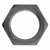
0012-0023
Description
HEX NUT FOR E13 SERIES SWITCH
Manufacturer
Cherry Electrical
Type
Sub-Miniature Snap-Action Switchesr
Series
0012r
Specifications of 0012-0023
Accessory Type
Hex Nut
Contact Form
SPDT
Contact Rating
25 Amps at 125 Volts, 250 Volts
Actuator
Lever, Hinge
Termination Style
Screw
Color
Natural
For Use With/related Products
CH100, CH101, CKN318, CH322, CH324, CH329
For Use With
CH574 - SWITCH SNAP SPDT .1A QC TERMCH329 - SWITCH SNAP 20A W/THD BUSHINGCH324 - SWITCH SNAP 15A W/THD BUSHINGCH322 - SWITCH SNAP 15A W/THD BUSHINGCH318 - SWITCH SNAP 25A W/THD BUSHINGCH101 - SWITCH SNAP SPDT 15A QC TERMCH100 - SWITCH SNAP SPDT 15A QC TERM
Lead Free Status / RoHS Status
Lead free / RoHS Compliant
Lead Free Status / RoHS Status
Lead free / RoHS Compliant, Lead free / RoHS Compliant
Other names
00120023
CH284
CH284


78
Glossary
TECHNICAL SECTION
Actuation Force
Force measured exactly when switch
changes state; when the actuator is
moved from rest to operating position.
Auxiliary Actuator
An external switch component that
will increase travel and/or reduce
the actuating force.
Actuation Length
The external actuatorʼs dimension
from the round (versus elongated)
mounting hole to the actuation line.
Break-Before-Make
This term is used in connection with
contacts where the moving contact,
in transferring from one position to
another, interrupts one circuit before
establishing the next.
Contact
In devices used for making and
breaking electrical currents, the
component that disengages to cause
the actual circuit rupture.
Contact Configuration
A desired arrangement of contacts/circuits.
See switch abbreviations, forms and poles.
Contact Gap
The distance between a pair of
open contacts.
Contact Pressure
Contact pressure is the amount of force
holding the movable and stationary contacts
together. While this should be termed
Contact Force, by convention in the
United States, it is called Contact Pressure.
Contact Resistance
The junction resistance between
two contacts, but usually measured at
contact terminals. It includes the terminal
resistance. Measuring volts and amps
should be similar to intended application.
Contact Wipe
Sliding of one contact over another during
actuation of switch.
Crosspoint
Gold contact prisms are welded at right
angles to each other providing maximum
contact pressure and minimum hazard
of contact closure interference. Used
exclusively for low energy switching.
Dielectric Strength
The property of an insulating material
which determines the maximum potential
gradient that the material can withstand
without rupture.
Double Break
A form of switch contact construction in
which a current carrying member bridges
a gap at two adjacent points, one at each
end of the bridging member.
Form A
A single pole, single throw, normally
open contact or SPST NO.
Form B
A single pole, single throw, normally
closed contact or SPST NC.
Form C
A single pole double throw contact or SPDT.
2-Form C
A double pole, double throw contact or DPDT.
High Ratio Position
The actuator mounting position
closest to the switch button.
Make
A term used to indicate that a switch
has completed the dynamics of closing
an electrical circuit.
Momentary Action
The circuit is either opened or closed,
only as long as the switch is actuated.
Normally Open
A term used to describe contacts
that are open in the rest position.
Normally Closed
A term used to describe contacts
which establish a circuit when in
the rest position.
Agency Approvals
Government Listings
Cage Code:
Federal ID:
Federal
Business Code: 03680
Poles
The number of separate circuits that can be
activated through a switch at any one time.
Reference Line
Also known as datum line. Used as a basis
for calculating the operating characteristics
of a switch.
Standard Ratio Position
The actuator mounting position
furthest from the switch button.
Switch Abbreviations
SPST: Single pole single throw
SPDT: Single pole double throw
DPST: Double pole single throw
DPDT: Double pole double throw
3PDT: Three pole double throw
4PDT: Four pole double throw
5PDT: Five pole double throw
Throw
The number of circuit paths that can be
controlled by one pole.
File E23301
Canadian approval
through UL
File 16503 — Canada
Canadian Standards Associa-
tion
File E23301
(per UL 1054 for special
use switches) — USA
Underwriters Laboratories, Inc.
File No. on Request —
VDE Verband Deutscher
Electrotechniker
01963
36-2977756
Related parts for 0012-0023
Image
Part Number
Description
Manufacturer
Datasheet
Request
R

Part Number:
Description:
MOUSE, LASER WIRELESS IR, USB, BLUE/BLK
Manufacturer:
Cherry Electrical
Datasheet:

Part Number:
Description:
Manufacturer:
Cherry Electrical
Datasheet:
Part Number:
Description:
Manufacturer:
Cherry Electrical
Datasheet: