4200-003 Storm Interface, 4200-003 Datasheet - Page 4
4200-003
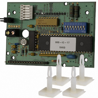
Manufacturer Part Number
4200-003
Description
ENCODER UNIVERSAL FOR KEYPADS
Manufacturer
Storm Interface
Specifications of 4200-003
Overall Dimensions
89 mm × 66 mm
Lead Free Status / RoHS Status
Lead free / RoHS Compliant
Other names
4200-001
4200-002
MGR1602
4200-002
MGR1602


Section 3. Communications Protocol
This document is provided for use and guidance of engineering personnel engaged in the installation or application of STORM data entry products manufactured by Keymat Technology Ltd. Please be
advised that all information, data, and illustrations contained within this document remain the exclusive property of Keymat Technology Ltd. and are provided for the express and exclusive use as de-
scribed above. This document is not supported by Keymat Technology’s engineering change note, revision or reissue system. Data contained within this document is subject to periodic revision, reis-
sue or withdrawal. Whilst every effort is made to ensure the information, data and illustrations are correct at the time of publication, Keymat Technology Ltd. are not responsible for any errors or omis-
sions contained within this document.
Physical Link Layer
The module transmits and receives data using RS232 signalling with a voltage swing of approximately ±9V. DIP Con-
figuration Switch 8 selects between 9600 baud (DIP switch off) and 1200 baud (DIP Switch on). In both conditions, 8-
bit data is used with no parity and one stop bit. This may be summarised as follows….
DIP8 OFF
DIP8 ON
No software or hardware handshaking is used since the data rate is low relative to the bandwidth of the communica-
tions protocol.
Only the TX, RX and Ground signals are employed. The chosen nomenclature is that TX means transmission out of
the module.
Data buffering
Both data transmission and reception are controlled by the module’s built in microprocessor using a pair of stacks-
one for transmitted characters and one for received characters. These allow the application to send data to and from
the unit largely without consideration of the timing constraints of the RS232 physical link layer.
Provided the stacks are not filled, data can be freely sent to and received from the module and the module will buffer
the characters until such times as it is able to process them.
The buffer sizes are as follows…
Data transmission (keypad data out of module)
Data reception (LCD data into module)
Should the buffers be filled, further characters will not be pushed onto the stacks, but instead are discarded.
Character echoing
Characters received from the host terminal/microprocessor may be echoed back to the host by setting DIP Configu-
ration Switch 2 to ON. With DIP Switch 2 OFF the characters are not echoed.
Characters resulting from key strokes are never echoed to the LCD display, but are simply sent via the RS232 TX pin
to the host application.
9600,8,N,1
1200,8,N,1
420 Series RS232 Encoder / Application/Engineering Manual Version 1.0 Jan 2004
420 Series RS232 Encoder for Keypad Applications
Application / Engineering Manual
16 bytes
48 bytes
Page 4
Related parts for 4200-003
Image
Part Number
Description
Manufacturer
Datasheet
Request
R


Part Number:
Description:
ENCODER, RS232
Manufacturer:
Storm Interface
Datasheet:


Part Number:
Description:
KEYPAD, STORM 1000, 12WAY
Manufacturer:
Storm Interface
Datasheet:

Part Number:
Description:
KEYPAD, STORM 700, 4WAY, BLACK
Manufacturer:
Storm Interface
Datasheet:

Part Number:
Description:
KEYPAD, STORM 700, 12WAY, GREY
Manufacturer:
Storm Interface
Datasheet:

Part Number:
Description:
KEYPAD, STORM 700, 12WAY, BLACK
Manufacturer:
Storm Interface
Datasheet:

Part Number:
Description:
KEYPAD, STORM 700, 16WAY, GREY
Manufacturer:
Storm Interface
Datasheet:

Part Number:
Description:
KEYPAD, STORM 700, 16WAY, BLACK
Manufacturer:
Storm Interface
Datasheet:

Part Number:
Description:
KEYPAD, STORM 700, QWERTY GREY
Manufacturer:
Storm Interface
Datasheet:

Part Number:
Description:
KEYPAD, STORM 700, QWERTY BLACK
Manufacturer:
Storm Interface
Datasheet:

Part Number:
Description:
KEYPAD, STORM 700, 4WAY, GREY
Manufacturer:
Storm Interface
Datasheet: