A22K-K Omron, A22K-K Datasheet - Page 21
A22K-K
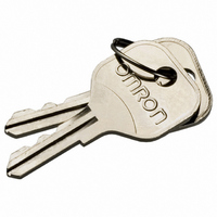
Manufacturer Part Number
A22K-K
Description
REPLACEMENT KEY A22 SERIES 2 PCS
Manufacturer
Omron
Type
Pushbutton Switchr
Specifications of A22K-K
Accessory Type
Replacement Key
Termination Style
Crimp
For Use With/related Products
A22K Series
For Use With
A22K-3MC-20 - SWITCH KEYLOCK 3POS ALT DPST-NOA22K-3MC-10 - SWITCH KEYLOCK 3POS ALT SPST-NOA22K-3MC-02 - SWITCH KEYLOCK 3POS ALT DPST-NCA22K-3MC-01 - SWITCH KEYLOCK 3POS ALT SPST-NCA22K-3AC-20 - SWITCH KEYLOCK 3POS MOM DPST-NOA22K-3AC-10 - SWITCH KEYLOCK 3POS MOM SPST-NOA22K-3AC-02 - SWITCH KEYLOCK 3POS MOM DPST-NCA22K-2ML-20 - SWITCH KEYLOCK 2POS ALT DPST-NOA22K-2ML-11 - SWITCH KEYLOC 2POS ALT DPST-NO/CA22K-2ML-02 - SWITCH KEYLOCK 2POS ALT DPST-NCA22K-2ML-01 - SWITCH KEYLOCK 2POS ALT SPST-NCA22K-2M-20 - SWITCH KEYLOCK 2POS ALT DPST-NOA22K-2M-11 - SWITCH KEYLOC 2POS ALT SPST-NO/CA22K-2M-02 - SWITCH KEYLOCK 2POS ALT DPST-NCA22K-2M-01 - SWITCH KEYLOCK 2POS ALT SPST-NCA22K-2AL-20 - SWITCH KEYLOCK 2POS MOM DPST-NOA22K-2AL-11 - SWITCH KEYLOC 2POS MOM SPST-NO/CA22K-2AL-02 - SWITCH KEYLOCK 2POS MOM DPST-NCA22K-2AL-01 - SWITCH KEYLOCK 2POS MOM SPST-NCA22K-3ML - SWITCH UNIT KEYLOCK ALT 3POS BLKA22K-3MC - SWITCH UNIT KEYLOCK ALT 3POS BLKA22K-3M - SWITCH UNIT KEYLOCK ALT 3POS BLKA22K-3AC - SWITCH UNIT KEYLOCK MOM 3POS BLKA22K-2ML - SWITCH UNIT KEYLOCK ALT 2POS BLKA22K-2M - SWITCH UNIT KEYLOCK ALT 2POS BLKA22K-2AL - SWITCH UNIT KEYLOCK MOM 2POS BLKZ1536 - SWITCH KEY 3-POS SPST-NO/NC BLKZ1535 - SWITCH KEY 3-POS SPST-NO/NC BLKZ1534 - SWITCH KEY 3-POS SPST-NO/NC BLKZ1533 - SWITCH KEY 3-POS SPST-NO/NC BLKZ1532 - SWITCH KEY 2POS SPST-NO BLACKZ1531 - SWITCH KEY 2POS SPST-NO BLACKZ1530 - SWITCH KEY 2POS SPST-NO BLACK
Lead Free Status / RoHS Status
Lead free / RoHS Compliant
Other names
A22K-K
A22KK
Z1669
A22KK
Z1669


Technical Information
•
•
Storage
•
•
Create gap
When performing soldering with a dip soldering bath, ensure that
the flux does not reach a higher level than the PCB.
Flux is especially likely to rise up at the edges of the PCB. If the
Switch is mounted near the edge of the PCB, create a gap
between the edge by using a split PCB, and insert the PCB in the
soldering bath so that the edge that is farthest from the Switch
enters the bath first.
When the Switch is left unused or stored for long periods, the
ambient conditions can have a great effect on the condition of the
Switch. In certain environments, leaving the Switch exposed
may result in deterioration (i.e., oxidation, or the creation of an
oxide film) of the contacts and terminals, causing the contact
resistance to increase, and making it difficult to solder the lead
wires. Therefore, store in a well-ventilated room, inside, for
example, a non-hygroscopic case, in a location where no
corrosive gases are present.
If the Switch is stored in a location where it will be exposed to
direct light, colored resin in the colored plate may fade.
Therefore, do not store the Switch in locations where it will be
exposed to direct light.
Split PCB
Incorrect
Correct
Flux is
more likely
to rise at
the edges.
Create distance
Insert in soldering
bath from this
edge.
Technical Information
19
Related parts for A22K-K
Image
Part Number
Description
Manufacturer
Datasheet
Request
R

Part Number:
Description:
SWITCH KEY 2POS SPST-NO BLACK
Manufacturer:
Omron
Datasheet:

Part Number:
Description:
SWITCH KEYLOCK 2POS MOM SPST-NC
Manufacturer:
Omron
Datasheet:
Part Number:
Description:
SWITCH KEYLOCK 2POS ALT SPST-NC
Manufacturer:
Omron
Datasheet:
Part Number:
Description:
SWITCH KEYLOCK 2POS ALT SPST-NC
Manufacturer:
Omron
Datasheet:

Part Number:
Description:
SWITCH KEY 3-POS SPST-NO/NC BLK
Manufacturer:
Omron
Datasheet:
Part Number:
Description:
SWITCH KEYLOCK 3POS ALT DPST-NO
Manufacturer:
Omron
Datasheet:
Part Number:
Description:
SWITCH KEYLOCK 2POS MOM DPST-NC
Manufacturer:
Omron
Datasheet:

Part Number:
Description:
SWITCH KEYLOC 2POS MOM SPST-NO/C
Manufacturer:
Omron
Datasheet:
Part Number:
Description:
SWITCH KEYLOCK 2POS MOM DPST-NO
Manufacturer:
Omron
Datasheet:
Part Number:
Description:
SWITCH KEYLOCK 2POS ALT DPST-NC
Manufacturer:
Omron
Datasheet:
Part Number:
Description:
SWITCH PB RND MOM SPST-NO/NC RED
Manufacturer:
Omron
Datasheet:

Part Number:
Description:
SWITCH PB ROUND ALT SPST-NO BLUE
Manufacturer:
Omron
Datasheet:

Part Number:
Description:
SWITCH PB ROUND ALT SPST-NO BLK
Manufacturer:
Omron
Datasheet:

Part Number:
Description:
SWITCH PB ROUND ALT SPST-NO GRN
Manufacturer:
Omron
Datasheet:

Part Number:
Description:
SWITCH PB ROUND ALT SPST-NO RED
Manufacturer:
Omron
Datasheet: