30-0002 APEM Components, 30-0002 Datasheet
30-0002
Specifications of 30-0002


Related parts for 30-0002


30-0002 Summary of contents
Page 1
... BS RIA 20 Shock & Vibration EN 61058-1 • Panel cut-out : - round or square : Ø (.866) - rectangular : 29,5 x 21,5 mm (1.160x.846) - flush mount : Ø (1.378) • 1 and 2 poles • Screw terminals (optional : quick-connect term.) • Contacts : silver • Current/voltage rating : 12A 380VAC 16A 250VAC max. - 25mA 5VAC min. ...
Page 2
... Solder heat resistance : (IEC 68-2-20Tb, method 2) • Degree of environmental protection (IEC 529 ) • Lamps : • Switch terminals : • Lamp terminals : Specifications for emergency stop switches : see pages 10 and 22. For screen engraving or film legends, contact APEM. G-4 ELECTRICAL SPECIFICATIONS A01 - A1 - A03 Momentary or maintained action 10mA 5VAC min ...
Page 3
... J1 - Led 12V red J2 - Led 12V green J3 - Led 12V amber J4 - Led 12V blue J5 - Led 12V white K1 - Led 24V red K2 - Led 24V green K3 - Led 24V amber K4 - Led 24V blue K5 - Led 24V white L1 - Led 48V red L2 - Led 48V green L3 - Led 48V amber 3 2 7.65 (.301) G G-5 ...
Page 4
... A01 series Illuminated or non-illuminated pushbutton switches Panel cut-out Ø 16 (.630) A pushbutton assembly requires : screen + lamp (if illuminated) + operator + switch block. To order these elements, select desired model numbers from tables below. Example : IP65 rectangular pushbutton, single pole, maintained, red screen and 12V red LED = A0161B, A0142M1, A0101X and A0151BUL ...
Page 5
... A0142N2 24V amber A0142N3 24V blue A0142N4 24V white A0142N5 48V red A0142P1 48V green A0142P2 48V amber A0142P3 www.apem.com Indicators Panel cut-out Ø 16 (.630) 24.00 18.00 (.945) (.709) 0.50 2.80 (.020) (.110) 8.50 (.335) Part No A0171 A0172 A0173 Ø ...
Page 6
... A019411 A019311• pos. momentary A019412 A019312• pos. maintained A019405 A019305 pos. momentary A019406 A019306 pos. mainL, momR A019407 A019307 pos. momL, mainR A019408 A019308 pos. maintained A019609 A019509• pos. momentary A019610 A019510• pos. maintained A019611 A019511• ...
Page 7
... A Three pole A0155BUL Four pole A0153BUL NON-REMOVABLE KEY POSITIONS / ON-ON-ON FUNCTION : contact APEM. A ‘pos’ - position, ‘mainL’ - maintained left, www.apem.com Keylock switches Panel cut-out Ø 16 (.630) 1 12.00 (.472) 6.00 (.236) 24.00 (.945 2.80 (.110) 18.00 30.70 (.709) (1.209) Key Positions ...
Page 8
... A01 series Emergency stop switches Panel cut-out Ø 16 (.630) • Prominent 24 mm (.944) dia. or optional 40 mm (1.575) dia. red mushroom actuator • Highly reliable positive break switch • Push to shut off switch, twist to reset to ON • Approved to UL 1054 / EN 60947-5-1 An emergency stop switch assembly requires : operator + switch block. ...
Page 9
... Yellow maintained A01MXDSP352B + PEA01 Green maintained A01MXESP352B + PEA01 Blue maintained A01MXFSP352B + PEA01 OPTIONS 12A 250V versions or custom printing on mushroom head actuators : contact APEM. APEM A01 series Emergency stop switches/mushroom head pushbutton switches www.apem.com Fitted in enclosures N.C. Emergency stop Momentary & maintained Ø40.0 (1 ...
Page 10
... A01 series Mushroom head pushbutton switches Panel cut-out Ø 16 (.630) • Prominent 24 mm (.944) dia. or optional 40 mm (1.575) dia. mushroom actuators • Momentary and maintained functions Momentary function versions are unmarked. Maintained function versions are twist release (arrows indicate direction of twist) • ...
Page 11
... Round, anodised aluminium A01FMM Round, matt black A01FMMG 18.00 (.708) 10.25 7.65 7.65 (.403) 5.00 (.301) (.301) (.196) 1.10 4.25 (.043) (.167) 4.25 (.167) 24.00 24.00 (.945) (.945) 13.65 (.537) Rectangular A01FG1 Square/round A01FG2 www.apem.com ...
Page 12
... BLANKING PLUGS RESISTOR ASSEMBLY A0152B + RISSP G-14 Slot as alternative to Ø hole - Material : 1 mm thick aluminium. 18.00 12.00 (.708) (.472) Ø2.00 (.078DIA) Ø16.00 (.630DIA) (.630DIA) Rectangular A01MG1 Square A01MG Ø16.00 (.629DIA) 18.00 2.00 (.708) (.078) For non-illuminated pushbuttons A0163AL 10.50 10.00 14.85 ( ...
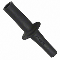
Page 13
... No 30-0001. • Wire chosen switch block as required and slide onto operator until latch engages. • Fit bulb if required using tool No 30-0002. • Snap screen onto reflector assembly with legend in between if required and snap onto front operator TAKING CARE TO LINE UP THE LOCATING SLOT WITH THE POLARISING DOT, and not to damage the seal ...