B32-1080 Omron, B32-1080 Datasheet - Page 7
B32-1080
Manufacturer Part Number
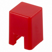
B32-1080
Description
KEYCAP 4MM SQ RED FITS 6MM SER
Manufacturer
Omron
Series
B32r
Type
Key Cap for Mechanical Key Switchesr
Specifications of B32-1080
Features
Dustproof construction ensures highly reliable performance at low voltage and very small
Switch Type
Tactile
Shape
Square
Color
Red
Illumination
Non-Illuminated
Mounting Type
Slip On
Size
4.00mm L x 4.00mm W x 5.50mm H
Application
Key to Top Designed Specially
Height
4 mm
Illumination Color
Red
Length
4 mm
Width
2.5 mm
Thread Size
6 mm x 6 mm
Actuator / Cap Color
Red
Length/height, External
5.5mm
External Width
4mm
Knob / Dial Style
Square
External Height
4mm
Mounting Style
Panel
Standards
RoHS Compliant
For Use With
SW792 - SWITCH TACT 6MM 150GF SPST SMDSW791 - SWITCH TACT 6MM 100GF SPST SMDB3F-6152 - SWITCH TACT 6MM 150GF H=7.3MM (B3F-6150 - SWITCH TACT 6MM 100GF H=7.3MM (SW799 - SWITCH TACT 6MM 150GF H=7.3MMSW798 - SWITCH TACT 6MM 100GF H=7.3MMSW1052 - SWITCH TACT 6MM 260GF H=6.15MMSW850 - SWITCH TACT 6.5MM 150GF H-7.3MMSW795 - SWITCH TACT 6MM 260GF H=7.3MMSW964 - SWITCH TACT 6MM 100GF H=7.3MMSW405 - SWITCH TACT 6MM MOM 150GFSW420 - SWITCH TACT 6MM MOM 230GF SEALEDSW419 - SWITCH TACT 6MM MOM 160GF SEALEDSW410 - SWITCH TACT 6MM RT ANG 150GFSW409 - SWITCH TACT 6MM RT ANG 100GFSW404 - SWITCH TACT 6MM MOM 100GF
Lead Free Status / RoHS Status
Lead free / Not applicable
For Use With/related Products
B3F and B3W Series
Lead Free Status / Rohs Status
Lead free / RoHS Compliant
Other names
B321080
SW252
SW252
Available stocks
Company
Part Number
Manufacturer
Quantity
Price
Company:

Part Number:
B32-1080
Manufacturer:
OMRON
Quantity:
12 000


Precautions
Safety Precautions
■
Use the Switch within the rated voltage and current ranges, other-
wise the Switch may have a shortened life expectancy, radiate
heat, or burn out. This particularly applies to the instantaneous
voltages and currents when switching.
■
Storage
To prevent degradation, such as discoloration, in the terminals
during storage, do not store the Switch in locations that are sub-
ject to the following conditions.
Handling
1. Operation
Do not repeatedly operate the Switch with excessive force. Apply-
ing excessive pressure or applying additional force after the
plunger has stopped may deform the disc spring of the Switch,
resulting in malfunction. In particular, applying excessive force to
Side-operated Switches may damage the caulking, which in turn
may damage the Switch. Do not apply force exceeding the maxi-
mum (29.4 N for 1 minute, one time) when installing or operating
Side-operated Switches.
Be sure to set up the Switch so that the plunger will operate in a
straight vertical line. A decrease in the life of the Switch may
result if the plunger is pressed off-center or from an angle.
2. Dust Protection
Do not use Switches that are not sealed in dust-prone environ-
ments. Doing so may cause dust to penetrate inside the Switch
and cause faulty contact. If a Switch that is not sealed must be
used in this kind of environment, use a sheet or other measure to
protect it against dust.
PCBs
The Switch is designed for a 1.6-mm thick, single-side PCB.
Using PCBs with a different thickness or using double-sided,
through-hole PCBs may result in loose mounting, improper inser-
tion, or poor heat resistance in soldering. These effects will occur,
depending on the type of holes and patterns of the PCB. There-
fore, it is recommended that a verification test is conducted before
use.
If the PCBs are separated after mounting the Switch, particles
from the PCBs may enter the Switch. If PCB particles or foreign
particles from the surrounding environment, workbench, contain-
ers, or stacked PCBs become attached to the Switch, faulty con-
tact may result.
Soldering
1. General Precautions
Before soldering the Switch on a multilayer PCB, test to confirm
that soldering can be performed properly. Otherwise the Switch
may be deformed by the soldering heat on the pattern or lands of
the multilayer PCB.
1. High temperature or humidity
2. Corrosive gases
3. Direct sunlight
Precautions for Safe Use
Precautions for Correct Use
Incorrect Incorrect
Correct
Switch
Resin sheet
Plunger
Operating part
Do not solder the Switch more than twice, including rectification
soldering. An interval of five minutes is required between the first
and second soldering.
2. Automatic Soldering Baths (B3F, B3W, B3WN, B3M, B3J)
Soldering temperature: 260 ° C max.
Soldering time: 5 s max. for a 1.6-mm thick single-side PCB
Preheating temperature: 100°C max. (ambient temperature)
Preheating time: Within 60 s
Make sure that no flux will rise above the level of the PCB. If flux
overflows onto the mounting surface of the PCB, it may enter the
Switch and cause a malfunction.
3. Reflow Soldering (Surface Mounting)
Solder the terminals within the heating curve shown in the follow-
ing diagram.
B3S, B3SN, B3FS
Note:
The peak temperature may vary depending on the reflow bath
used. Confirm the conditions beforehand.
Do not use an automatic soldering bath for surface-mounted
Switches. The soldering gas or flux may enter the Switch and
damage the Switch’s push-button operation.
4. Manual Soldering (All Models)
Soldering temperature: 350 ° C max. at the tip of the soldering iron
Soldering time: 3 s max. for a 1.6-mm thick, single-side PCB
Before soldering the Switch on a PCB, make sure that there is no
unnecessary space between the Switch and the PCB.
Washing
1. Washable and Non-washable Models
Standard Switches are not sealed, and cannot be washed. Doing
so will cause the washing agent, together with flux or dust parti-
cles on the PCB, to enter the Switch, resulting in malfunction.
Washable (sealed types)
Non-washable (standard types) B3F, B3FS, B3M, B3J,
The above heating curve applies if the PCB thickness is
1.6 mm.
temperature
Max. 250
Room
220
180
150
Flux surface
PCB surface
60 to 120
Preheating
B3W, B3WN, B3S, B3SN
B3DA, B3D
Max. 60
Precautions
Time (s)
5
Related parts for B32-1080
Image
Part Number
Description
Manufacturer
Datasheet
Request
R

Part Number:
Description:
KEYCAP 4MM SQ ORANGE FOR 6MM B3F
Manufacturer:
Omron
Datasheet:

Part Number:
Description:
KEYCAP 12MM SQ ORANGE FITS 12MM
Manufacturer:
Omron
Datasheet:

Part Number:
Description:
KEYCAP 9MM LT GRN FITS 12MM
Manufacturer:
Omron
Datasheet:

Part Number:
Description:
KEYCAP 9MM SQ ORG FITS 12MM
Manufacturer:
Omron
Datasheet:

Part Number:
Description:
KEYCAP 12MM GRN FITS 12MM
Manufacturer:
Omron
Datasheet:

Part Number:
Description:
KEYCAP 9MM SQ GREEN FOR 12MM B3F
Manufacturer:
Omron
Datasheet:

Part Number:
Description:
KEYCAP 4MM LT GRN FITS 6MM
Manufacturer:
Omron
Datasheet:

Part Number:
Description:
KEYCAP 12MM LT GRN FITS 12MM
Manufacturer:
Omron
Datasheet:


Part Number:
Description:
KEYCAP 4MM SQ BLUE FITS 6MM SER
Manufacturer:
Omron
Datasheet:

Part Number:
Description:
B3F ROUND KEY CAP LT GRAY
Manufacturer:
Omron
Datasheet:

Part Number:
Description:
Tactile Switch Key Top
Manufacturer:
OMRON [Omron Electronics LLC]
Datasheet:
Part Number:
Description:
Tactile Switch Key Top
Manufacturer:
OMRON [Omron Electronics LLC]
Datasheet: