A16ZA-5101G Omron, A16ZA-5101G Datasheet - Page 26
A16ZA-5101G
Manufacturer Part Number
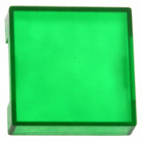
A16ZA-5101G
Description
CAP 16 SERIES SQUARE GREEN
Manufacturer
Omron
Series
A16r
Type
Cap, Squarer
Specifications of A16ZA-5101G
Switch Type
Pushbutton
Shape
Square
Color
Green
Illumination
Illumination Optional
Mounting Type
Snap Fit
Size
15.10mm L x 15.10mm W x 3.50mm H
Cap Color
Green
Length
18 mm
Mounting Style
Snap On
Width
18 mm
For Use With/related Products
A16 Series
Lead Free Status / RoHS Status
Lead free / RoHS Compliant
For Use With
A16, M16 Series
Lead Free Status / RoHS Status
Lead free / RoHS Compliant, Lead free / RoHS Compliant
Other names
A16ZA5101G


A16/M16
Precautions
Mounting
Always make sure that the power is turned OFF before mounting,
removing, or wiring the Switch, or performing maintenance.
Do not tighten the mounting nut more than necessary using tools
such as pointed-nose pliers. Doing so will damage the mounting
nut. The tightening torque is 0.29 to 0.49 N m.
Wiring
Solder terminals and quick-connect terminals (#110) are commonly
used for terminals.
Be sure to use electrical wires that are a size appropriate for the
applied voltage and carry current (conductor size is 0.5 to 0.75
mm
below. If the soldering is not properly performed, the lead wires will
become detached, resulting in short-circuits.
1. Hand soldering: 30 W, within 5 s
2. Dip soldering: 240 C, within 3 s
Wait for one minute after soldering before exerting any external
force on the solder.
Use non-corrosive resin fluid as the flux.
Make sure that the electric cord is wired so that it does not touch the
Unit. If the electric cord touches the Unit, then electric wires with a
heat resistance of 100 C min. must be used.
After wiring the Switch, maintain an appropriate clearance and
creepage distance.
Operating Environment
The IP65 model is designed with a protective structure so that it will
not sustain damage if it is subjected to water from any direction to
the front of the panel.
Using the Microload
Insert a contact protection circuit, if necessary, to prevent the reduc-
tion of life expectancy due to extreme wear on the contacts caused
by loads where inrush current occurs when the contact is opened
and closed.
Do not apply a voltage between the incandescent lamp and
the terminal that is greater than the rated voltage. If the incan-
descent lamp is broken, the operating part may pop out.
Always turn OFF the power and wait for 10 minutes before
replacing the incandescent lamp. If the lamp is replaced
immediately after the power is turned OFF, the remaining heat
may cause burns.
Correct Use
2
). Perform soldering according to the conditions provided
!
WARNING
The A16 allows both a standard load (125 V at 5A, 250 V at 3 A) and
a microload. If a standard load is applied, however, the microload
area cannot be used. If the microload area is used with a standard
load, the contact surface will become rough, and the opening and
closing of the contact for a microload may become unreliable.
The minimum applicable load is the N-level reference value. This
value indicates the malfunction reference level for the reliability
level of 60% ( 60) (conforming to JIS C5003).
The equation,
malfunction rate is less than 1/2,000,000 with a reliability level of
60%.
LED
The LED current-limiting resistor is built-in, so internal resistance is
not required.
Note: The values in parentheses are for models with blue Push-
Others
The oil-resistant IP65 uses NBR rubber and is resistant to general
cutting oil and cooling oil. Some particular oils cannot be used with
the oil-resistant IP65, however, so contact your OMRON represen-
tative for details.
5 VDC
12 VDC
24 VDC
button Units.
Rated voltage
60 = 0.5 x 10
Invalid
area
–4
/time indicates that the estimated
33
270
1600
Area of use
Internal limiting resistor
(82 )
(470 )
(2400 )
Current (mA)
A16/M16
77
Related parts for A16ZA-5101G
Image
Part Number
Description
Manufacturer
Datasheet
Request
R

Part Number:
Description:
LEGEND PANEL SQUARE OPAQUE
Manufacturer:
Omron
Datasheet:
Part Number:
Description:
LEGEND PANEL IP40 SQ TRANSP
Manufacturer:
Omron
Datasheet:
Part Number:
Description:
LEGEND PANEL IP65 SQ TRANSP
Manufacturer:
Omron
Datasheet:

Part Number:
Description:
PANEL PLUG SQUARE
Manufacturer:
Omron
Datasheet:
Part Number:
Description:
SQUARE DUST COVER
Manufacturer:
Omron
Datasheet:
Part Number:
Description:
CAP 16 SERIES SQUARE BLUE
Manufacturer:
Omron
Datasheet:
Part Number:
Description:
CAP 16 SERIES SQUARE GREEN
Manufacturer:
Omron
Datasheet:
Part Number:
Description:
CAP 16 SERIES SQUARE RED
Manufacturer:
Omron
Datasheet:
Part Number:
Description:
CAP 16 SERIES SQUARE WHITE
Manufacturer:
Omron
Datasheet:
Part Number:
Description:
CAP 16 SERIES SQUARE YELLOW
Manufacturer:
Omron
Datasheet:

Part Number:
Description:
SWITCH PB SQUARE MOM SPDT GREEN
Manufacturer:
Omron
Datasheet:
Part Number:
Description:
SWITCH PB SQUARE MOM SPDT WHITE
Manufacturer:
Omron
Datasheet:
Part Number:
Description:
SWITCH PB SQUARE MOM SPDT YELLOW
Manufacturer:
Omron
Datasheet:
Part Number:
Description:
SWITCH PB RECTANG MOM SPDT BLUE
Manufacturer:
Omron
Datasheet:
Part Number:
Description:
SWITCH PB RECTANG MOM SPDT YEL
Manufacturer:
Omron
Datasheet: