A165L-AW Omron, A165L-AW Datasheet - Page 22
A165L-AW
Manufacturer Part Number
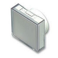
A165L-AW
Description
CAP 16 SERIES SQUARE WHITE
Manufacturer
Omron
Series
A16r
Specifications of A165L-AW
Switch Type
Pushbutton
Shape
Square
Color
White
Illumination
Illumination Optional
Mounting Type
Snap Fit
Size
15.10mm L x 15.10mm W x 3.50mm H
Lens Width
15.1mm
Svhc
No SVHC (15-Dec-2010)
Colour
White
Height
3.5mm
Lens Colour
White
Lens Height
3.5mm
Rohs Compliant
Yes
For Use With
A16 Series Pushbutton Switches
Lead Free Status / RoHS Status
Lead free / RoHS Compliant
For Use With/related Products
A16 Series
Lead Free Status / Rohs Status
Lead free / RoHS Compliant
Other names
A165LAW


Dimensions
PCB Terminals (Lamp terminals are also present on non-lighted models.)
Terminal Arrangement
Voltage-reduction Lighting (Lamp terminals are also present on non-lighted models.)
Solder Terminals
• The voltage-reduction circuit is built in.
Note: Secure the panel to the board using stud bolts
A = 24 min.: Rectangular
A = 21 min.: Square or round
L = 24 min.
Use a PCB with a thickness of 1.6 mm.
(Bottom View)
PCB Cutouts
Dimensions of
PCB Terminals
2.7
if force will be applied to the board after wiring.
Lamp terminal (t=0.5)
0.8
1.5
DPDT lighted models
(Bottom view)
3.5
20 ± 0.1 4.85 ± 0.05
5.3
12.4 ± 0.05
Side with TOP indicated
Side with direction arrow
Five, 1 dia.
Model, rating, and lot
number indication
Lighted SPDT Switches
6.3 ± 0.05
NC
NO
C
L
L
4.85
12.4
18.6
NC
NO
C
Two, 5 dia.
Side with TOP indicated
A ± 0.1
Terminal Arrangement
(Bottom View)
Screw-Less Clamps
Red (Release button)
White (Release button)
Black (Release button)
Black (Release button)
• Voltage-reduction lighting models with Screw-Less Clamps (A16L-@T1-2S, A16L-@T2-2S)
incorporate voltage-reduction circuits.
COM
SW 1
NC
NO
L-
L ± 0.1
A = 24 min.: Rectangular
A = 21 min.: Square or round
L = 24 min.
Use a PCB with a thickness of 1.6 mm.
Note: Secure the panel to the board using stud bolts
Dimensions of
PCB Terminals
(Bottom View)
PCB Cutouts
Lamp terminal (t=0.5)
2.7
if force will be applied to the board after wiring.
0.8
1.5
3.5
20 ± 0.1
5.3
DPDT lighted models
Red (Release button)
12.4 ± 0.05
Black (Release button)
Side with TOP indicated
4.85 ± 0.05
Lighted DPDT Switches
12-3.1 dia. (Insertion hole)
Red (Release button)
White (Release button)
Black (Release button)
Black (Release button)
6.3 ± 0.05
4.85
12.4
18.6
Two, 5 dia.
Terminal Arrangement
Side with TOP indicated
(Bottom View)
6.3 ± 0.05
A ± 0.1
SW 1
COM
Side indicating TOP
NC
NO
NC2
NO2
C2
C2
L-
SW 2
COM
NC
NO
(Unit: mm)
-
+
+
A16
NC1
NO1
C1
C1
L ± 0.1
Eight, 1 d
22
Related parts for A165L-AW
Image
Part Number
Description
Manufacturer
Datasheet
Request
R

Part Number:
Description:
SWITCH PB SQ ALT DPDT GREEN
Manufacturer:
Omron
Datasheet:
Part Number:
Description:
SWITCH PB SQ MOM DPDT GREEN
Manufacturer:
Omron
Datasheet:
Part Number:
Description:
SWITCH PB SQ ALT DPDT RED
Manufacturer:
Omron
Datasheet:
Part Number:
Description:
SWITCH PB SQ MOM DPDT RED
Manufacturer:
Omron
Datasheet:
Part Number:
Description:
SWITCH PB SQ ALT DPDT WHITE
Manufacturer:
Omron
Datasheet:
Part Number:
Description:
SWITCH PB SQ MOM DPDT WHITE
Manufacturer:
Omron
Datasheet:
Part Number:
Description:
SWITCH PB SQ ALT DPDT YELLOW
Manufacturer:
Omron
Datasheet:
Part Number:
Description:
SWITCH PB SQ MOM DPDT YELLOW
Manufacturer:
Omron
Datasheet:
Part Number:
Description:
SWITCH PB RECT ALT DPDT GREEN
Manufacturer:
Omron
Datasheet:
Part Number:
Description:
SWITCH PB RECT MOM DPDT GREEN
Manufacturer:
Omron
Datasheet:
Part Number:
Description:
SWITCH PB RECT MOM DPDT RED
Manufacturer:
Omron
Datasheet:
Part Number:
Description:
SWITCH PB RECT ALT DPDT WHITE
Manufacturer:
Omron
Datasheet:
Part Number:
Description:
SWITCH PB RECT MOM DPDT WHITE
Manufacturer:
Omron
Datasheet: