A165L-TB Omron, A165L-TB Datasheet - Page 15
A165L-TB
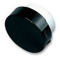
Manufacturer Part Number
A165L-TB
Description
CAP 16 SERIES ROUND BLACK
Manufacturer
Omron
Series
A16r
Specifications of A165L-TB
Switch Type
Pushbutton
Shape
Round
Color
Black
Illumination
Non-Illuminated
Mounting Type
Snap Fit
Size
15.10mm Dia x 3.50mm H
Svhc
No SVHC (15-Dec-2010)
Colour
Black
External Diameter
15.1mm
Height
3.5mm
Panel Cutout Diameter
16mm
Mounting Hole Dia
16mm
Lens Colour
Black
Lens Height
3.5mm
Lens Diameter
15.1mm
Rohs Compliant
Yes
For Use With
A16 Series Pushbutton Switches
Lead Free Status / RoHS Status
Lead free / RoHS Compliant
For Use With/related Products
A16 Series
Lead Free Status / Rohs Status
Lead free / RoHS Compliant
Other names
A165LTB


A16 / M16
Installation
After mounting the Pushbutton Unit to the panel, snap in the Socket
Unit from the back of the panel.
Mounting the Panel
Insert the Pushbutton Unit into the front of the panel, and fix the lock
ring and mounting nut from the terminal side.
Make sure that the lock ring is aligned with the thread of the case
and the edge of the lock ring is touching the panel.
Tighten the mounting nuts to a torque of 0.20 to 0.39 N
5 kgf cm).
The maximum tightening torque is 0.39 N m (5 kgf cm).
Switch Mounting
Snap on the Switch Unit to the Pushbutton Unit.
Make sure the the Switch Unit is in the proper orientation when
snapping on to the Pushbutton Unit.
Switch Removal
Grip the part between the Switch holder of the case and the Switch
Unit using the A16Z-5080 Extractor, and pull to remove the Switch
Unit.
Mounting the Panel
Case
A16Z-5080 Extractor
Edge
Thread
Panel
Lock ring
Mounting nut
m (3 to
ing Part
Removing and Mounting the Operating Part
Removing the Lamp
Removing from the Operating Part End
Removing from the Switch Unit End
The Lamp can be removed by hand once the Switch is removed
using the A16Z-5080 Extractor.
Installing the Lamp
When mounting the Lamp, make sure it is facing the direction shown
in the following diagram. Insert the Lamp while matching the pro-
truding part of the Lamp and the small guides on the outer surface of
the case.
The Lamp can be mounted from the operating part end by using the
A16Z-5080 Extractor. The lamp can be mounted by following the
opposite procedure for removing the Lamp.
1. Remove the operating part as shown in the following
2. To attach the operating part, push until it clicks into place.
Mounting and Replacing the Operat-
diagram. If the operating part cannot be removed by hand,
use the A3PJ-5080 Extractor.
Protruding part
Lamp
Grip the Lamp with the
A16Z-5080 Extractor and
pull to remove.
Operating section
A16 / M16
15
Related parts for A165L-TB
Image
Part Number
Description
Manufacturer
Datasheet
Request
R

Part Number:
Description:
SWITCH PB SQ ALT DPDT GREEN
Manufacturer:
Omron
Datasheet:
Part Number:
Description:
SWITCH PB SQ MOM DPDT GREEN
Manufacturer:
Omron
Datasheet:
Part Number:
Description:
SWITCH PB SQ ALT DPDT RED
Manufacturer:
Omron
Datasheet:
Part Number:
Description:
SWITCH PB SQ MOM DPDT RED
Manufacturer:
Omron
Datasheet:
Part Number:
Description:
SWITCH PB SQ ALT DPDT WHITE
Manufacturer:
Omron
Datasheet:
Part Number:
Description:
SWITCH PB SQ MOM DPDT WHITE
Manufacturer:
Omron
Datasheet:
Part Number:
Description:
SWITCH PB SQ ALT DPDT YELLOW
Manufacturer:
Omron
Datasheet:
Part Number:
Description:
SWITCH PB SQ MOM DPDT YELLOW
Manufacturer:
Omron
Datasheet:
Part Number:
Description:
SWITCH PB RECT ALT DPDT GREEN
Manufacturer:
Omron
Datasheet:
Part Number:
Description:
SWITCH PB RECT MOM DPDT GREEN
Manufacturer:
Omron
Datasheet:
Part Number:
Description:
SWITCH PB RECT MOM DPDT RED
Manufacturer:
Omron
Datasheet:
Part Number:
Description:
SWITCH PB RECT ALT DPDT WHITE
Manufacturer:
Omron
Datasheet:
Part Number:
Description:
SWITCH PB RECT MOM DPDT WHITE
Manufacturer:
Omron
Datasheet: