7814G-1-051E Bourns Inc., 7814G-1-051E Datasheet
7814G-1-051E
Manufacturer Part Number
7814G-1-051E
Description
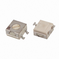
SWITCH 4MM SQ SPDT 50 LIFE SMD
Manufacturer
Bourns Inc.
Series
7814r
Datasheet
1.7814G-1-051E.pdf
(2 pages)
Specifications of 7814G-1-051E
Circuit
SPDT
Number Of Positions
2
Contact Rating @ Voltage
0.1A @ 16VDC
Actuator Type
Rotary for Tool
Actuator Level
Flush
Mounting Type
Surface Mount
Orientation
Top Actuated
Washable
No
No. Of Poles
1
No. Of Switch Positions
2
Rotational Life Cycles
50
Contact Current Max
100mA
Switch Function
SPDT
Rohs Compliant
Yes
Number Of Poles Per Deck
2
Number Of Decks
2
Contact Style
Non Shorting
Termination Style
SMD/SMT
Lead Free Status / RoHS Status
Lead free / RoHS Compliant
Other names
7814G-001-051E
7814G-051ETR
7814G-051ETR


Contact Rating
Contact Timing ..................Non-shorting
Contact Resistance ........... 2 ohms max.
Insulation Resistance
Dielectric Strength .................... 250 VAC
General Characteristics
Switch Type ...................................SPDT
Operating Temp. Range
Storage Temp. Range ..-55 °C to +125 °C
Seal Test ......................85 °C Fluorinert†
Mechanical Characteristics
Positions ...............................................2
Adjustment Torque ......... 1.8 N-cm max.
Stop Strength .................. 2.5 N-cm min.
Pushover Strength (Z Style)
Weight ................Approximately 0.2 gm.
Marking ........................... Manufacturer’s
Environmental Characteristics
Vibration ......................................... 20 G
Shock ........................................... 100 G
Thermal Shock ........................(5 cycles)
Humidity
Rotational Life
Packaging Options
Model
Terminal
Switch Type
Rotational Life
Optional Embossed Tape Designator
(For pin styles J, G, Z only - omit for tube
packaging)
*RoHS Directive 2002/95/EC Jan 27 2003 including Annex.
†“Fluorinert” is a registered trademark of 3M Co.
Specifi cations are subject to change without notice.
Customers should verify actual device performance in their specifi c applications.
Electrical Characteristics
Maximum Current ..........100 mA max.
Maximum Voltage ........................16 V
Insulation Resistance
-051 ..................................... 50 Cycles
-023 ................................. 2000 Cycles
J & G ..................................... 500 pcs.
Z ............................................ 200 pcs.
H ....................................100 pcs./tube
How to Order
1 = SPDT
............................. 100 megohms min.
............................... -55 °C to +125 °C
......................... 2 kilograms minimum
............................... 10 megohms min.
J = J-Hook
G = Gull Wing
H = Through-hole
Z = Right Angle
-051 = 50 Cycles
-023 = 2000 Cycles
trademark, life code and date code
7814 J - 1 - 051 E
-55 °C to +125 °C
Features
■
■
■
■
■
7814 SMD 4 mm Square Sealed Rotary Switch
(.197)
7814J
J-Hook
7814G
Gull Wing
(.031 ± .004)
5.00
(.244)
3 PLCS.
0.80 ± 0.10
(.177)
(.093)
6.20
(.039)
4.50
2.35
1.00
2 PLCS.
(.051 ± .004)
Circuit Diagram - 7814J, G ,H
Product Dimensions
Single pole/double throw
Compatible with most surface mount
manufacturing processes
50 or 2000 cycle rotational life
Compatible with popular vacuum pick-and-
place equipment
J-hook, gull-wing and through hole
1.30 ± 0.10
(.177)
CW
CCW
4.50
051
CW
(.197)
5.00
3
051
C
CCW
(.177)
7A
4.50
C
CCW
(.051 ± .004)
1.30 ± 0.10
7A
X
X
(.031 ± .004)
(.177)
0.80 ± 0.10
4.50
ADJUSTMENT
SLOT
(.096)
(.020)
(.022)
2.45
2 PLCS.
(.093)
0.51
0.55
2.35
C
2
X
X
ADJUSTMENT
SLOT
(.020)
(.020)
(.157)
(.096)
3 PLCS.
2.45
RECOMMENDED PCB LAYOUT
2 PLCS.
(.091)
0.51
0.51
LONG
WIDE
DEEP
RECOMMENDED PCB LAYOUT
4.0
(.051)
(.051)
2.30
1.30
1.3
(.079)
2.0
(.100)
LONG
WIDE
DEEP
2.55
5° MAX.
TYP.
1 CW
(.091)
(.024)
3 PLCS.
2.3
(.217)
0.60
TYP.
2 PLCS.
5.50
(.079)
(.079)
(.051)
(.008)
2.00
(.100)
1.30
2.0
TYP.
0.20
2.55
■
■
■
7814H
Through-
hole
(.248)
7814Z
Right Angle
(.226)
6.30
(.024)
3.18
0.61
(.100)
(.050)
Meets EIA/EIAJ/IPC/VRCI SMD standard
outline dimensions
RoHS compliant* - see
information
components
For switch applications/processing
guidelines,
2.54
1.27
1
Circuit Diagram - 7814Z
ROTOR POSITIONED AS SHOWN
WITHIN ± 22˚ OF CENTERLINE
OF TERMINAL 2
023
(.177)
DIMENSIONS:
TOLERANCES: ±2 EXCEPT WHERE NOTED.
CCW
4.50
C
(.177)
4.50
CW
3
051
2E
1
click here
(.177)
on lead free surface mount
4.50
C
X
X
CCW
(.024 ± .004)
(.100)
0.60 ± 0.10
2.55
ADJ. SLOT
(.095)
(.020)
(.024)
3 PLCS.
2.41
0.51
0.60
(.047)
7A
1.19
(.197)
5.01
(.050)
(INCHES)
1.29
LONG
WIDE
DEEP
MM
C
2
(.100)
(.051)
2.54
1.30
processing
RECOMMENDED PCB LAYOUT
(.197)
(.121)
(.080)
RECOMMENDED PCB LAYOUT
3.08
(.226)
5.00
(.138)
2.01
5.76
3.48
(.197 ± .004)
OUTSIDE WHEN
PINS ARE PARALLEL
(.157)
5.00 ± 0.10
TYP.
4.00
(.031)
3 CW
0.80
(.220)
5.60
(.100)
2.55
TYP. DIA.
(.010)
0.26
(.084)
(.008)
0.21
0.20
(.130)
3.32
(.100)
2.55
(.080)
(.038)
(.080)
2.01
2.01
0.96
TYP.
Related parts for 7814G-1-051E
Image
Part Number
Description
Manufacturer
Datasheet
Request
R

Part Number:
Description:
SWITCH 4MM SQ SPDT 2000 LIFE SMD
Manufacturer:
Bourns Inc.
Datasheet:

Part Number:
Description:
Manufacturer:
Bourns, Inc.
Datasheet:
Part Number:
Description:
11mm Potentiometer
Manufacturer:
Bourns, Inc.
Datasheet:
Part Number:
Description:
Manufacturer:
Bourns, Inc.
Datasheet:
Part Number:
Description:
Manufacturer:
Bourns, Inc.
Datasheet:
Part Number:
Description:
Manufacturer:
Bourns, Inc.
Datasheet:
Part Number:
Description:
5/16 Round Trimming Potentiometer
Manufacturer:
Bourns, Inc.
Datasheet:
Part Number:
Description:
4100R Series: Thick Film Moulded DIPs - Resistor Networks
Manufacturer:
Bourns, Inc.
Datasheet:
Part Number:
Description:
PROTECTOR - SINGLE BIDIRECTIONAL
Manufacturer:
Bourns, Inc.
7814G-1-051E Summary of contents
Page 1
... PLCS. 1.00 (.039) 3 PLCS. 1.3 (.051) 2 PLCS. 0.80 ± 0.10 2.3 (.031 ± .004) 2.35 (.091) (.093) 2 PLCS. 7814G Gull Wing 4.50 (.177) 5° MAX. C TYP. ADJUSTMENT SLOT 2.45 0.60 4.50 LONG (.096) (.024) (.177) 0.51 TYP. ...
Page 2
SMD 4 mm Square Sealed Rotary Switch Packaging Specifi cations (J Style) .36 MAX. (.014) 2.74 ± .10 (.101 ± .004) 5.52 ± 0.5 (.217 ± .020) 1.5 + .10/ –.00 DIA. (.059 + .004.–.00) 5.26 ± .10 (.207 ...