A6D-2100 Omron, A6D-2100 Datasheet - Page 3
A6D-2100
Manufacturer Part Number
A6D-2100
Description
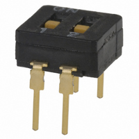
SWITCH DIP 2POS TOP ACT SEALED
Manufacturer
Omron
Series
A6Dr
Type
DIPr
Datasheets
1.A6ER-4104.pdf
(14 pages)
2.A6D-4100.pdf
(4 pages)
3.A6D-2100.pdf
(3 pages)
4.A6D-8103.pdf
(3 pages)
Specifications of A6D-2100
Circuit
SPST
Number Of Positions
2
Contact Rating @ Voltage
0.1A @ 5VDC
Actuator Type
Standard
Actuator Level
Flush
Mounting Type
Through Hole
Orientation
Top Actuated
Washable
Yes
Switch Type
DIL
Contact Configuration
SPST-CO
No. Of Switch Positions
2
Actuation Type
Flat
Pitch Spacing
2.54mm
Contact Current Dc Max
100mA
Switch Mounting
Through Hole
Svhc
Bis (2-ethyl(hexyl)phthalate)
Actuator
Switch
Terminal Pitch
2.54 mm
Termination Style
Solder Pin
Contact Rating
100 mA
Operating Temperature Range
- 20 C to + 70 C
Body Style
Subminiature
Current, Rating
30 mA
Dielectric Strength
500 VAC
Number Of Poles
2
Operation
Top-Actuated
Termination
Through Hole
Voltage, Rating
30 VDC
Actuator Style
Flat
Rohs Compliant
Yes
Lead Free Status / RoHS Status
Lead free / RoHS Compliant
Lead Free Status / RoHS Status
Lead free / RoHS Compliant, Lead free / RoHS Compliant
Other names
A6D-2100
A6D2100
SW896
A6D2100
SW896
Available stocks
Company
Part Number
Manufacturer
Quantity
Price
Company:

Part Number:
A6D-2100
Manufacturer:
OMRON
Quantity:
6 000


A6D
Precautions
The terminal pitch of all OMRON DIP switches is the same as a digi-
tal IC chip, which has a 2.54mm pitch. Moreover, Models A6C and
A6D DIP switches are also identical to an DIL-IC chip in shape, so
that they can be mounted on a PC board in exactly the same manner
as ordinary IC chips.
When using these OMRON DIP switches, pay attention to the fol-
lowing points:
Circuit Design
Design the circuit for the DIP switch so that the switch can be used
within the rated voltage and current ranges. The rated maximum
voltage and current must not be exceeded (even momentarily)
when the switch breaks or makes contact. The rated minimum cur-
rent is 10 A (at 3.5 VDC). When CMOS iCs are used on the same
PC board as the DIP switch, the momentary current applied to the
DIP switch can be increased to improve the contact reliability on
some occasions. At this time, however, the peak value of the current
must not exceed the rated maximum value.
Mounting
The rotor is set to position 0 at the factory. Do not move the rotor to
any other position, until after the switch has been mounted on a PC
board, soldered, cleaned and dried.
1.Automatic mounting
The top actuated types of models A6C and A6D are in the same
shape as DIL-IC packages. Therefore, an automatic IC chip
mounter can be used to mount these DIP switches without modifica-
tion or, at worst, by slightly modifying the stopper. (A body stopper is
recommended as the stopper for the shoot. Do not use a half-lead
stopper. However, this depends on the automatic chip mounter to be
used. Check the specifications of the chip mounter in advance.)
Use a PC board 1.2 to 1.6mm thick.
The mounting holes on the PC board should be 0.9mm or larger in
diameter.
2.Manual mounting or use of IC socket
Use a commercially available IC chip inserting tool.
IC sockets (such as OMRON model XR) can be used to mount the
DIP switch on a PC board as the terminal size and pitch of the switch
are the same as ordinary IC chips.
When manually inserting the DIP switch terminal into the mounting
holes on a PC board, position the Dip switch so that the terminals
can be inserted into the respective mounting holes on the PC board
(or on an IC socket) all at once. Then push down the switch as far as
it will go. Apply the force at right angles to the PC board. When
removing the DIP switch from the PC board or IC socket, do not twist
the tip of a screwdriver or similar object inserted between the switch
and the PC board or IC socket. Convenient pullout tools are com-
mercially available.
Soldering
Before soldering, confirm that all the terminals of the DIP switch
have been deeply inserted into the mounting holes on the PC board.
Dip the PC board on which the DIP switch(es) are mounted in the
solder flux. The flux must not come over the surface of the PC board.
Both hand and automatic soldering are possible, under the following
conditions:
Cleaning
Use freon TES to remove the solder flux. Dip the switch in an ultra-
sonic oven, a solution oven and a vapophase oven to a depth of
5cm, for 60 seconds each.
Ethyl acohol or isopropyl alcohol can also be used. If used, however,
finish the cleaning process within 5 minutes.
Do not use cleaning solvents other than these, as the switch materi-
als may degrade.
Operation
1
2.
3.
Hand soldering
Automatic
soldering
Use the tip of a standard screwdriver or similar object to oper-
ate the rotary DIP switch.
Use an appropriately sized screwdriver. If the tip is too large or
small, the groove of the actuator may be damaged or
deformed.
The actuators of a slide type DIP switch can be moved by a
stick or ball-point pen having a round tip. Do not use sharp
edged objects such as tweezers.
The top actuated types and side actuated types of the slide
DIP switches can also be operated with the fingers.
Flux
PC board
350_C
260_C
temperature
Max. solder
A6CV, A6DR
3 seconds
5 seconds
Max. solder time
A6C, A6D
A6D
3
Related parts for A6D-2100
Image
Part Number
Description
Manufacturer
Datasheet
Request
R

Part Number:
Description:
Slide Switch,STRAIGHT,DPST,ON-OFF,Number Of Positions:2,PC TAIL Terminal,PCB Hole Count:4
Manufacturer:
Omron
Datasheet:

Part Number:
Description:
Slide Switch,STRAIGHT,4PST,ON-OFF,Number Of Positions:2,PC TAIL Terminal,PCB Hole Count:8
Manufacturer:
Omron
Datasheet:

Part Number:
Description:
Slide Switch,STRAIGHT,4PST,ON-OFF,Number Of Positions:2,PC TAIL Terminal,PCB Hole Count:8
Manufacturer:
Omron
Datasheet:

Part Number:
Description:
Slide Switch,STRAIGHT,6PST,ON-OFF,Number Of Positions:2,PC TAIL Terminal,PCB Hole Count:12
Manufacturer:
Omron
Datasheet:

Part Number:
Description:
Slide Switch,STRAIGHT,8PST,ON-OFF,Number Of Positions:2,PC TAIL Terminal,PCB Hole Count:16
Manufacturer:
Omron
Datasheet:

Part Number:
Description:
Slide Switch,STRAIGHT,10PST,ON-OFF,Number Of Positions:2,PC TAIL Terminal,PCB Hole Count:20
Manufacturer:
Omron
Datasheet:
Part Number:
Description:
Slide Switch,STRAIGHT,5PST,ON-OFF,Number Of Positions:2,PC TAIL Terminal,PCB Hole Count:10
Manufacturer:
Omron
Datasheet:
Part Number:
Description:
Slide Switch,STRAIGHT,3PST,ON-OFF,Number Of Positions:2,PC TAIL Terminal,PCB Hole Count:6
Manufacturer:
Omron
Datasheet:
Part Number:
Description:
Slide Switch,STRAIGHT,3PST,ON-OFF,Number Of Positions:2,PC TAIL Terminal,PCB Hole Count:6
Manufacturer:
Omron
Datasheet:
Part Number:
Description:
Slide Switch,STRAIGHT,7PST,ON-OFF,Number Of Positions:2,PC TAIL Terminal,PCB Hole Count:14
Manufacturer:
Omron
Datasheet:
Part Number:
Description:
Slide Switch,STRAIGHT,7PST,ON-OFF,Number Of Positions:2,PC TAIL Terminal,PCB Hole Count:14
Manufacturer:
Omron
Datasheet:
Part Number:
Description:
Slide Switch,STRAIGHT,9PST,ON-OFF,Number Of Positions:2,PC TAIL Terminal,PCB Hole Count:18
Manufacturer:
Omron
Datasheet:

Part Number:
Description:
SWITCH DIP 8POS TOP ACT SEALED
Manufacturer:
Omron
Datasheet:
Part Number:
Description:
SWITCH DIP 10POS TOP ACT. SEALED
Manufacturer:
Omron
Datasheet:

Part Number:
Description:
SWITCH DIP 4POS TOP ACTUATED
Manufacturer:
Omron
Datasheet: