A22K-2AL-11 Omron, A22K-2AL-11 Datasheet - Page 199
A22K-2AL-11
Manufacturer Part Number
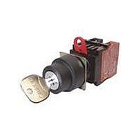
A22K-2AL-11
Description
SWITCH KEYLOC 2POS MOM SPST-NO/C
Manufacturer
Omron
Series
A22Kr
Specifications of A22K-2AL-11
Circuit
DPST (1-NO, 1-NC)
Number Of Positions
2
Contact Rating @ Voltage
10A @ 110VAC
Actuator Type
Flat Key
Mounting Type
Panel Mount
Termination Style
Screw Terminal
Key Removable Positions
Left
Angle Of Throw
90°
Contact Form
SPST - NO / NC
Switch Function
Alternate
Contact Rating
3 Amps
Lead Free Status / RoHS Status
Lead free / RoHS Compliant
Lead Free Status / RoHS Status
Lead free / RoHS Compliant, Lead free / RoHS Compliant
Other names
A22K2AL11


Terminal Connection
Note: The above terminal connection diagrams are examples for SPST-NO + SPST-NC and DPST-NC.
A Lock Ring is provided as a standard feature.
Note: 1. When painting or coating the panel, make sure that the
Installation
Preparing the Panel
• The panel dimensions are shown below.
• The panel thickness must be 1 to 5 mm.
• Always use a 25-mm-dia. Lock Ring for a 25-mm-dia. hole.
• When painting or coating the panel, make sure that the specified
Non-lighted
Lighted without Voltage
Reduction Unit
Lighted with Voltage
Reduction Unit
IP65 degree of protection will be lost if the 25-mm-dia. Lock Ring is
not used because of the larger size of a 25-mm-dia. hole.
panel dimensions apply to the panel after painting or coating.
3.2
Panel Cutouts
Mounting to the Panel
With Lock Fitting
3.2
+0.2
2. Use an A22Z-R25 Ring when mounting to a panel with a 25-
22.3
0
+0.2
0
specified panel dimensions apply to the panel after painting
or coating.
mm diameter hole.
With Lock Ring
Type
+0.4
0
22.3
dia.
R0.8 max.
+0.4
0
24.1
R0.8 max.
dia.
+0.4
0
24.1
+0.4
0
22.3
1
2
Without Lock Fitting
1
2
+0.4
SPST-NO + SPST-NC
0
22.3
dia.
1
2
X1
X2
+0.4
Without Lock Ring
0
( )
( )
X1
X2
dia.
25
Terminal connection (BOTTOM VIEW)
X
+0.5
0
3
4
25
dia.
X
+0.5
0
3
4
dia.
3
4
Mounting the Operation Unit on the
Panel
Insert the Operation Unit (Pushbutton) from the front surface of the
panel, insert the Lock Ring and the mounting nut from the terminal
side, then tighten the nut. Before tightening, check that the rubber
washer is present between the Operation Unit and the panel.
When using a Legend Plate Frame, put one rubber washer each
between the Legend Plate Frame and the panel and between the
Operation Unit and the Legend Plate Frame. (One rubber washer will
be provided when one Legend Plate Frame is ordered.)
Align the Lock Ring with the groove in the casing, then insert the
Lock Ring so that its edge is located on the panel side.
Tighten the mounting nut at a torque of 0.98 to 1.96 N·m.
When using a Lock Ring, replace with the supplied Lock Ring, insert
the projecting part into the lock slot, and then tighten the mounting
nut.
1
2
1
2
1
2
X1
X2
DPST-NC
( )
( )
X1
X2
X
1
2
X
1
2
1
2
197
Related parts for A22K-2AL-11
Image
Part Number
Description
Manufacturer
Datasheet
Request
R

Part Number:
Description:
REPLACEMENT KEY A22 SERIES 2 PCS
Manufacturer:
Omron
Datasheet:

Part Number:
Description:
Switch, Selector, 22mm, 10A, SPST-NO, 2 Position
Manufacturer:
Omron Automation
Datasheet:
Part Number:
Description:
Switch, Selector, 1NO-1NC CONTACT, 2 Position MAINTAINED, LEFT-RIGHT KEY RELEASE
Manufacturer:
Omron Automation
Datasheet:
Part Number:
Description:
Switch, Keylock, 2 Pos, DPST-NO
Manufacturer:
Omron Automation
Datasheet:

Part Number:
Description:
SWITCH KEY 2POS SPST-NO BLACK
Manufacturer:
Omron
Datasheet:

Part Number:
Description:
SWITCH KEYLOCK 2POS MOM SPST-NC
Manufacturer:
Omron
Datasheet:
Part Number:
Description:
SWITCH KEYLOCK 2POS ALT SPST-NC
Manufacturer:
Omron
Datasheet:
Part Number:
Description:
SWITCH KEYLOCK 2POS ALT SPST-NC
Manufacturer:
Omron
Datasheet:
Part Number:
Description:
SWITCH KEYLOCK 2POS MOM DPST-NC
Manufacturer:
Omron
Datasheet:
Part Number:
Description:
SWITCH KEYLOCK 2POS MOM DPST-NO
Manufacturer:
Omron
Datasheet:
Part Number:
Description:
SWITCH PB RND MOM SPST-NO/NC RED
Manufacturer:
Omron
Datasheet:

Part Number:
Description:
SWITCH PB ROUND ALT SPST-NO BLUE
Manufacturer:
Omron
Datasheet:

Part Number:
Description:
SWITCH PB ROUND ALT SPST-NO BLK
Manufacturer:
Omron
Datasheet:

Part Number:
Description:
SWITCH PB ROUND ALT SPST-NO GRN
Manufacturer:
Omron
Datasheet:

Part Number:
Description:
SWITCH PB ROUND ALT SPST-NO RED
Manufacturer:
Omron
Datasheet: