MB2461E1W01 NKK Switches, MB2461E1W01 Datasheet - Page 4
MB2461E1W01
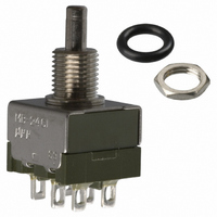
Manufacturer Part Number
MB2461E1W01
Description
SWITCH PB DPDT MOM 3A SOLDER LUG
Manufacturer
NKK Switches
Series
MB2400r
Type
Standardr
Specifications of MB2461E1W01
Circuit
DPDT
Switch Function
On-Mom
Contact Rating @ Voltage
3A @ 125VAC
Actuator Type
Plunger for Cap
Mounting Type
Panel Mount
Termination Style
Solder Lug
Contact Form
DPDT
Current, Rating
3 A
Dielectric Strength
1500 VAC
Mounting Hole Size
0.256 "
Number Of Poles
2
Number Of Positions
2
Operation
On-(On)
Termination
Solder
Voltage, Rating
125 VAC
Lead Free Status / RoHS Status
Lead free / RoHS Compliant
Illumination Type, Color
-
Illumination Voltage (nominal)
-
Lead Free Status / Rohs Status
RoHS Compliant part
Other names
360-2152
MB2461E1W01-RO
MB2461E1W01-RO


NKK Switches
Pole
DP
SP
Standard Hardware: .068” (1.74mm)
(8.0) Dia
.315
(8.0) Dia
.315
E1
E2
Maximum Panel Thickness with
For A1, A2, S1, or S2 Bushing
MB2411
MB2461
Note: Plunger selection is not required for MB2400 pushbuttons. The plunger can be used with or without a cap.
.285” (7.24mm)
Threaded with D Flat
.285” (7.24mm)
Smooth with D Flat
Model
(6.5) Dia
.256
with Keyway
.098
(2.5)
(2.5)
.098
(2.84) Dia
(2.84) Dia
.112
.112
.024
(0.6)
Normal
1/4-40 Thd
.220
(5.54)
.244
ON
ON
(5.54)
(5.6)
(6.2) Dia
.218
.218
( ) = Momentary
Plunger Position
Keyway
Hardware is illustrated following the Typical Switch Dimension drawings.
(7.24)
(7.24)
.285
.285
.035
.035
(0.9)
(0.9)
Standard hardware includes 2 hex nuts & 1 lockwasher.
Down
(ON)
(ON)
Snap-Action Bushing Mount
A1
A2
(8.0) Dia
.315
(8.0) Dia
.315
Standard Hardware: .068” (1.74mm)
Maximum Panel Thickness with
(0.8)
.031
.031
(0.8)
POLES & CIRCUITS
.280” (7.1mm)
Threaded with Keyway
.280” (7.1mm)
Smooth with Keyway
For E1 or E2 Bushing
(6.5) Dia
.256
1-3 4-6
Normal
BUSHINGS
Connected Terminals
Panel Cutouts
1-3
with D Flat
Keyway
.098
(2.5)
.098
(2.5)
(2.84) Dia
.112
(2.84) Dia
.112
1/4-40 Thd
(5.8)
.228
(5.54)
.218
(6.2) Dia
.244
(5.54)
.218
1-2 4-5
Down
1-2
.280
(7.1)
.280
(7.1)
.035
(0.9)
.035
(0.9)
(8.0) Dia
.315
Series MB2400
SPDT
DPDT
(8.0) Dia
.315
Note: Terminal numbers are
S1
S2
Standard Hardware: .134” (3.40mm)
Throw & Switch Schematics
.031
(0.8)
.031
(0.8)
Maximum Panel Thickness with
Optional Locking Ring
not actually on the switch.
.350” (8.9mm)
Threaded with Keyway
.350” (8.9mm)
Smooth with Keyway
3
(6.5) Dia
.256
(2.2) Dia
.087
.098
(2.5)
.098
(2.5)
With
3
1
(COM)
(2.84) Dia
.112
(2.84) Dia
.112
2
1/4-40 Thd
1
.244
(5.54)
6
(6.2) Dia
(COM)
.218
(5.54)
(6.5)
.256
.218
2
4
.350
.350
(8.9)
(8.9)
5
.035
(0.9)
.035
(0.9)
Related parts for MB2461E1W01
Image
Part Number
Description
Manufacturer
Datasheet
Request
R

Part Number:
Description:
PWR SPLY MEDICAL LINEAR 24V 1.2A
Manufacturer:
SL Power Electronics Manufacture of Condor/Ault Brands
Datasheet:

Part Number:
Description:
SURFACE MOUNT SCHOTTKY BARRIER RECTIFIER
Manufacturer:
PANJIT [Pan Jit International Inc.]
Datasheet:

Part Number:
Description:
Rocker Switches & Paddle Switches High In-rush Rated Rocker Switch
Manufacturer:
NKK Switches
Datasheet:
Part Number:
Description:
Rocker Switches & Paddle Switches High In-rush Rated Rocker Switch
Manufacturer:
NKK Switches
Datasheet:
Part Number:
Description:
Rocker Switches & Paddle Switches High In-rush Rated Rocker Switch
Manufacturer:
NKK Switches
Datasheet:
Part Number:
Description:
Rocker Switches & Paddle Switches High In-rush Rated Rocker Switch
Manufacturer:
NKK Switches
Datasheet:

Part Number:
Description:
Pushbutton Switches SPST ON(OFF) 15/32'
Manufacturer:
NKK Switches
Datasheet:

Part Number:
Description:
Pushbutton Switches SPST OFF(ON) 15/32'
Manufacturer:
NKK Switches
Datasheet:

Part Number:
Description:
Pushbutton Switches ON(OFF) NORM CLSD 3A RED PLNGR LUG 15/32
Manufacturer:
NKK Switches
Datasheet:

Part Number:
Description:
Pushbutton Switches SPDT ON-(ON)
Manufacturer:
NKK Switches
Datasheet:

Part Number:
Description:
Pushbutton Switches ON-(ON) RND BUSH MNT RED LED RED/RED CAP
Manufacturer:
NKK Switches
Datasheet:
Part Number:
Description:
Pushbutton Switches SPST ON-(OFF) STRT
Manufacturer:
NKK Switches
Datasheet:
Part Number:
Description:
Pushbutton Switches OFF(ON) NORM OPEN 3A RED CAP LUG 15/32
Manufacturer:
NKK Switches
Datasheet:
Part Number:
Description:
Pushbutton Switches ILLUM PUSHBUTTON SPDT
Manufacturer:
NKK Switches
Datasheet:
Part Number:
Description:
Pushbutton Switches OFF(ON) NORM OPEN 3A BLK CAP LUG 15/32
Manufacturer:
NKK Switches
Datasheet: