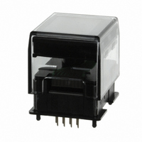
ISC15ANP4 NKK Switches, ISC15ANP4 Datasheet - Page 3

ISC15ANP4
Manufacturer Part Number
ISC15ANP4
Description
SWITCH OLED 64RGB X 48
Manufacturer
NKK Switches
Series
SmartSwitch™r
Type
OLED Displayr
Datasheet
1.ISC15ANP4.pdf
(5 pages)
Specifications of ISC15ANP4
Mfg Application Notes
OLED SmartSwitch/Display Appl Notes
Circuit
SPST-NO
Switch Function
Off-Mom
Contact Rating @ Voltage
0.1A @ 12VDC
Actuator Type
Rectangular Button
Illumination Type, Color
OLED, Red/Green/Blue
Mounting Type
Through Hole
Termination Style
PC Pin
Contact Form
SPST
Contact Rating
3.8 mA
Actuator
Square, Full Guard
Supply Voltage
2.8 V
Mounting Style
Snap In
Contact Material
Gold
Illumination
Illuminated
Mounting Angle
Straight
Pole Throw Configuration
SPST
Switch Function Configuration
N.O.
Current Rating (max)
0.1A
Operating Temp Range
-20C to 70C
For Use With
360-2423 - SMARTSWITCH EVAL KIT OLED PB360-2339 - KIT DEV FOR OLED SWITCH
Lead Free Status / RoHS Status
Lead free / RoHS Compliant
Illumination Voltage (nominal)
-
Lead Free Status / Rohs Status
Lead free / RoHS Compliant
Other names
360-2344
OLED SMARTSWITCH
NKK Switches • email: smartswitch@nkkswitches.com • Phone (480) 991-0942 • Fax (480) 998-1435 • www.nkksmartswitch.com
SWITCH BLOCK DIAGRAM & PIN CONFIGURATIONS
TYPICAL SWITCH DIMENSIONS
(0.20) Typ
.0079
(20.59)
(0.03) Typ
.0012
.811
See
Pixel Detail
(11.6)
.457
Pixel Detail
Pin No.
10
1
2
3
4
5
6
7
8
9
.0083
.0012
(0.21) Typ
(0.03)
(15.5)
See Pixel
Detail A
.610
(13.41)
.528
Typ
(23.13)
Symbol
.911
GND
D/C
SCK
RES
SW
SW
SDI
V
V
OLED SMARTSWITCH
SS
DD
CC
Pixel Detail A
(0.04) Typ
.0016
(0.07) Typ
.0028
.0067
(0.17)
.0079
(0.20)
(0.74)
(9.57)
.029
.377
.0083
R
R
(0.21)
G B R
Terminal of Switch
Terminal of Switch
Power
Slave Select
Reset
Data/Command
Serial Clock
Serial Data In
Power
Ground
TM
Name
Standoff 1 = (2.7)
Standoff Detail
(23.0)
.906
Dimension A
.106
RES
D/C
V
V
SCK
SS
SDI
GND 10
SW
DD
CC
.008
(0.2)
3
4
Standoff 2 = (2.3)
9
5
7
8
6
1
Normally open
Normally open
Power source for logic circuit
Slave select for SPI. This line is active low.
Reset signal input. When pin is low, initialization of chip is
executed.
Data/Command Control. When pin is pulled low, data will
be interpreted as Command; when pulled high, data will be
interpreted as Data.
Clock line for SPI that synchronizes command and data
Data input line for SPI
Power source for drive circuit
Connect to Ground
See Standoff
Detail
(3.3)
.130
(3.4)
.134
.024
.016
(0.6)
(0.4)
A
TM
Typ
Typ
(2.0) Dia
.079
Graphic Display
96 x 64 x 16 Bit
(1.25)
Data
MCU Interface
.049
Gray Scale
.091
Decoder
SR1,SG1,SB1......SR64,
Function
Segment Driver
SG64,SB64
RAM
Footprint
Color OLED Panel
Terminal numbers are not on the switch.
(16.0)
8x (0.75)
.630
64RGB x 48
Standoff 1
Standoff 2
.039
.029
(1.0)
Command Decoder
(7.62)
.276
.300
(7.0)
Driving Block
(0.3)
.012
SEG/COM
Typ
Dia
(2.0)
.079
Typ
COM1....COM48
Common Driver
Display Timing
Generator
Oscillator
3
9
2
1
10
4
(8.0)
.315
(7.05)
.278
(18.0)
.709
(18.0)
.709
(7.05)
.278
(8.0)
.315
10
4
2
1
OLED Driver
with Controller
9
3
2
(0.2)
.008
.079
(7.62)
(2.0)
SW
.300
Standoff 1
Standoff 2
4x (1.3) Dia
Landless
2x (0.9)
.039
(1.0)
(7.0)
.276
Typ
.051
.035
(16.0)
.630
Typ
Dia
4


