1241.6664.1124000 Schurter Inc, 1241.6664.1124000 Datasheet - Page 19
1241.6664.1124000
Manufacturer Part Number
1241.6664.1124000
Description
SWITCH MSM30 RI 5A @125VAC BLUE
Manufacturer
Schurter Inc
Type
Vandal Resistant, Illuminatedr
Series
MSMr
Datasheets
1.1241.6611.1120000.pdf
(22 pages)
2.1241.6624.1124000.pdf
(22 pages)
3.1241.6624.1124000.pdf
(21 pages)
Specifications of 1241.6664.1124000
Switch Function
On-Mom
Termination Style
Quick Connect - .110" (2.8mm)
Circuit
SPDT
Contact Rating @ Voltage
5A @ 125VAC
Actuator Type
Flush Round Button
Illumination Type, Color
LED, Blue
Illumination Voltage (nominal)
24 VDC
Mounting Type
Panel Mount
Contact Form
SPDT
Contact Rating
5 Amps at 250 volts
Actuator
Button, Round
Mounting Style
Panel
Terminal Seal
Sealed
Contact Plating
Silver
Contact Material
Silver
Illumination
Illuminated
Illumination Color
Blue
Body Length
33.4 mm
Body Shape
Round
Current Rating (max)
5 Amps
Housing Material
Stainless Steel
Insulation Resistance
100 MOhms
Led Supply Voltage
24 Volts
Mounting Angle
Straight
Operating Force
4.5 N
Voltage Rating Ac
250 Volts
Water / Moisture Rating
IP40
Body Style
Micro
Current, Rating
5/3 A
Ip Rating
IP67
Mounting Hole Size
30 mm
Special Features
Illuminated
Termination
Quick Connect
Voltage, Rating
125/250 VAC
Lead Free Status / RoHS Status
Lead free / RoHS Compliant
Lead Free Status / RoHS Status
Lead free / RoHS Compliant, Lead free / RoHS Compliant
Other names
486-1131


SCHURTER GmbH
D – 79346 Endingen
www.schurter.com
4
Legend
19 of 22
4.1
4.2
Seite
During assembly, the protruding bars of the holder should not be pressed together.
I
II
III
IV
V
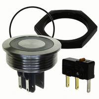
ASSEMBLY
General Instruction
Installation
Erstelldatum:
05.11.2004
= Housing
= Flat pin terminals (illumination)
= Gasket
= Screw Nut
= Micro Switch element
Ersteller:
Ullmer
Changes that contribute to technical improvement are subject to alternations
Änderungsdatum: Geändert von:
25.03.2010
Schillak
Installation instruction
Installation information:
1. Place the Gasket accurately on the actuator
2. Tighten the screw Nut with the torque
3. Clasp the micro switch into the micro switch
1. The power supply and the configuration of
2. Insulate the terminals as required
3. Installation instructions according to VDE-
housing. Then mount the actuator
housing assembly into the panel.
instructions according to
holder of the actuator housing.
the flat pin terminals has to be installed
correctly for the illumination and micro
switch function.
standard DIN VDE 0100-100 or
alternatively IEC 60354 standard
10177
Änderungs-Nr.
Datenblatt Nr.
105.9502
Print date: 25/03/2010 09:46:00
Chapter 2.5
Index
n
Related parts for 1241.6664.1124000
Image
Part Number
Description
Manufacturer
Datasheet
Request
R

Part Number:
Description:
MSM22 RI SF 10 A 250VAC GN
Manufacturer:
Schurter Inc
Datasheet:
Part Number:
Description:
LSH-Taster 6x6mm / 7,00mm-Blistergurt, taped and reeled
Manufacturer:
Schurter Inc
Part Number:
Description:
Fuse Drawer Quick Connect Snap-In
Manufacturer:
Schurter Inc
Datasheet:
Part Number:
Description:
Power Entry Module Filtered M 3 POS 250VAC 1A Switch/Fuse ST 1 Port
Manufacturer:
Schurter Inc
Datasheet:
Part Number:
Description:
Power Entry Module Filtered M 3 POS 250VAC 10A Switch/Fuse ST 1 Port
Manufacturer:
Schurter Inc
Datasheet:
Part Number:
Description:
Power Entry Module Filtered M 3 POS 250VAC 4A Switch/Fuse ST 1 Port
Manufacturer:
Schurter Inc
Datasheet:
Part Number:
Description:
Power Entry Module Filtered M 3 POS 250VAC 2A Switch/Fuse ST 1 Port
Manufacturer:
Schurter Inc
Datasheet:
Part Number:
Description:
6765 POWER ENTRY MODUL 10A 70C
Manufacturer:
Schurter Inc
Datasheet:
Part Number:
Description:
0102 APPLIANCE OUTLET FOR CABLE 10A 155
Manufacturer:
Schurter Inc