HB215SKG03CE NKK Switches, HB215SKG03CE Datasheet - Page 4
HB215SKG03CE
Manufacturer Part Number
HB215SKG03CE
Description
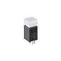
SWITCH PB ILLUM SPST SQ RED/YEL
Manufacturer
NKK Switches
Series
HB2r
Type
Illuminatedr
Specifications of HB215SKG03CE
Circuit
SPST-NO
Switch Function
Off-Mom
Contact Rating @ Voltage
0.4VA @ 28VAC/DC
Actuator Type
Plunger for Cap
Illumination Type, Color
LED, Red/Yellow
Illumination Voltage (nominal)
2.0, 2.1 VDC
Mounting Type
Through Hole
Termination Style
PC Pin
Contact Form
SPST
Contact Rating
0.4 Volt-Amp at 28 VoltsAC/DC
Actuator
Square
Supply Voltage
28 VoltsAC/DC
Mounting Style
Through Hole
Contact Plating
Gold
Contact Material
Phosphor Bronze
Illumination
Illuminated
Illumination Color
Red, Yellow
Body Shape
Square
Current Rating (max)
0.4 Volt-Amp
Dielectric Strength
500 VoltsAC
Features
Quiet actuation combined with crisp tactile feedback suited for broadcast equipment; sliding twin crossbar
Housing Material
Polyamide, Glass Fiber Reinforced
Insulation Resistance
500 MOhms
Led Supply Voltage
2 Volts, 2.1 Volts
Mounting Angle
Straight
Operating Force
1.8 N
Power Capacity (va)
0.4 Volt-Amp
Voltage Rating Ac
28 Volts
Voltage Rating Dc
28 Volts
Lead Free Status / RoHS Status
Lead free / RoHS Compliant


NKK Switches • email: sales@nkkswitches.com • Phone (480) 991-0942 • Fax (480) 998-1435
Pole
S
G03
SP
If the source voltage is greater than rated LED voltage, a ballast resistor must be connected in series with the LED. The circuit
Where: R
Electrical specifications are determined at a basic temperature of 25°C. LED circuit is independent of switch operation.
.307" Square Body
E
HB215
Gold Contacts
Model
R =
E
V
I
F
F
+
–
= Resistor Value (Ohms)
= Source Voltage (V)
= Forward Voltage (V)
= Forward Current (mA)
diagram and formula above will assist in calculating the value of the required ballast resistor.
E - V
R
I
F
V F
F
Switch Terminal
Normal
I F
(0.4)
.016
(
(0.5) Sq
.020
OFF
Plunger Position
) = Momentary
CONTACT MATERIALS, RATINGS, & TERMINALS
(3.5)
.138
Quiet Actuation Illuminated Pushbutton
Down
(ON)
BICOLOR LEDS & SPECIFICATIONS
Forward Peak Current
Continuous Forward Current
Forward Voltage
Reverse Peak Voltage
Current Reduction Rate Above 25°C
Ambient Temperature Range
HOUSING SHAPE & COLOR
Logic Level
LED is an integral part
of the HB2 switch.
Lamp Terminal
Connected Terminals
POLE & CIRCUIT
Normal
(0.4)
(0.5) Sq
.020
OPEN
.016
(3.5)
.138
K
Down
1-2
Black Housing
Color
I
I
V
V
∆I
(0.85) Dia Typ
(2.5) Typ
.098
FM
F
.033
SPST
Notes: Switch terminals are not marked on switch.
F
RM
.039
F
(1.0) Dia
PCB Footprint
Throw & Switch/Lamp Schematics
0.4VA maximum @ 28V AC/DC
.020
(0.5)
Red LED terminal is marked with “R”.
LED circuit is isolated and requires
external power source.
Red/Yellow
0.33/0.33
2.0/2.1
30/30
20/20
C L
4/4
CE
1
www.nkkswitches.com
-25°C ~ +50°C
(2.25) Typ
.039
.089
(1.0) Dia
(2.54)
.100
(0.92)
2
.036
Series HB2
Red/Green
0.33/0.33
2.0/2.1
3 (+)
5 (+)
30/30
20/20
Yellow or Green
4/4
CF
Red
4 (-)
mA/°C
Unit
mA
mA
V
V
L-5
Related parts for HB215SKG03CE
Image
Part Number
Description
Manufacturer
Datasheet
Request
R

Part Number:
Description:
Rocker Switches & Paddle Switches High In-rush Rated Rocker Switch
Manufacturer:
NKK Switches
Datasheet:
Part Number:
Description:
Rocker Switches & Paddle Switches High In-rush Rated Rocker Switch
Manufacturer:
NKK Switches
Datasheet:
Part Number:
Description:
Rocker Switches & Paddle Switches High In-rush Rated Rocker Switch
Manufacturer:
NKK Switches
Datasheet:
Part Number:
Description:
Rocker Switches & Paddle Switches High In-rush Rated Rocker Switch
Manufacturer:
NKK Switches
Datasheet:

Part Number:
Description:
Pushbutton Switches SPST ON(OFF) 15/32'
Manufacturer:
NKK Switches
Datasheet:

Part Number:
Description:
Pushbutton Switches SPST OFF(ON) 15/32'
Manufacturer:
NKK Switches
Datasheet:

Part Number:
Description:
Pushbutton Switches ON(OFF) NORM CLSD 3A RED PLNGR LUG 15/32
Manufacturer:
NKK Switches
Datasheet:

Part Number:
Description:
Pushbutton Switches SPDT ON-(ON)
Manufacturer:
NKK Switches
Datasheet:

Part Number:
Description:
Pushbutton Switches ON-(ON) RND BUSH MNT RED LED RED/RED CAP
Manufacturer:
NKK Switches
Datasheet:
Part Number:
Description:
Pushbutton Switches SPST ON-(OFF) STRT
Manufacturer:
NKK Switches
Datasheet:
Part Number:
Description:
Pushbutton Switches OFF(ON) NORM OPEN 3A RED CAP LUG 15/32
Manufacturer:
NKK Switches
Datasheet:
Part Number:
Description:
Pushbutton Switches ILLUM PUSHBUTTON SPDT
Manufacturer:
NKK Switches
Datasheet:
Part Number:
Description:
Pushbutton Switches OFF(ON) NORM OPEN 3A BLK CAP LUG 15/32
Manufacturer:
NKK Switches
Datasheet:
Part Number:
Description:
Pushbutton Switches SPST NO Metric Thrd Blk Plunge w/Blu Cap
Manufacturer:
NKK Switches
Datasheet:
Part Number:
Description:
Pushbutton Switches SPST OFF-(ON) NO 3A
Manufacturer:
NKK Switches
Datasheet: