LB26SKW01 NKK Switches, LB26SKW01 Datasheet - Page 2
LB26SKW01
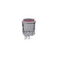
Manufacturer Part Number
LB26SKW01
Description
SW PB DPDT ALT SQ SILV SLD MNT
Manufacturer
NKK Switches
Series
LBr
Type
Standardr
Specifications of LB26SKW01
Circuit
DPDT
Switch Function
On-On
Contact Rating @ Voltage
3A @ 125VAC
Actuator Type
Plunger for Cap
Mounting Type
Panel Mount, Snap-In
Termination Style
Solder, Quick Connect - .110" (2.8mm)
Pole Throw Configuration
DPDT
Switch Configuration
ON ON
Actuator Style
Square Button
Current Rating (max)
3A
Illumination Type
Not Required
Ac Voltage Rating (max)
250VVAC
Dc Voltage Rating (max)
30VVDC
Contact Material
Silver Alloy
Contact Plating
Silver
Mechanical Life
200000
Product Height (mm)
34mm
Product Depth (mm)
17.8mm
Operating Temp Range
-25C to 70C
Mounting Style
Panel
Terminal Type
Quick Connect/Solder
Contact Form
DPDT
Contact Rating
3 Amps at 125 Volts, 250 Volts
Actuator
Button, Square
Supply Voltage
125 Volts, 250 Volts
Terminal Seal
Epoxy
Illumination
Not Illuminated
Illumination Color
Red
Flammability Rating
UL 94 V-0
Body Length
21.5 mm
Body Shape
Square
Dielectric Strength
1000 Volts
Features
Latchdown feature gives indication of circuit status
Housing Material
Polyamide, Glass Fiber Reinforced
Insulation Resistance
200 MOhms
Led Supply Voltage
250 Volts
Mounting Angle
Vertical
Operating Force
5.39 N
Body Style
Standard
Current, Rating
3 A
Electrical Life
100000 Operations (Min.)
Force, Operating
4.41 N
Material, Casing
Glass Fiber Reinforced Polyamide
Material, Contact
Silver
Material, Terminal
Brass with Silver Plating
Mounting Hole Size
0.638"L×0.638"W
Number Of Poles
2
Number Of Positions
2
Operation
On-On
Resistance, Contact
50 Milliohms (Max.)
Resistance, Insulation
200 Megohms (Min.) @ 500 VDC
Special Features
Illuminated, Alternate Legend
Standards
UL Recognized, CSA Certified
Temperature, Operating
-25 to +50 °C
Termination
Solder/Quick Connect
Voltage, Rating
250/30 VAC/VDC
Lead Free Status / RoHS Status
Lead free / RoHS Compliant
Illumination Type, Color
-
Illumination Voltage (nominal)
-
Lead Free Status / Rohs Status
Compliant


General Specifications
NKK Switches
Electrical Capacity (Resistive Load)
Other Ratings
Materials & Finishes
Environmental Data
Installation
Standards & Certifications
R
Soldering Time & Temperature:
Nominal Operating Force:
Flammability Standards:
Operating Temp Range:
UL & C-UL Recognized:
Cap Installation Force:
Insulation Resistance:
Quick Connect Force:
Stationary Contacts:
Power Level (silver):
Contact Resistance:
Dielectric Strength:
Logic Level (gold):
Movable Contact:
Switch Terminals:
Lamp Terminals:
Mechanical Life:
Contact Timing:
Snap-in Frame:
CSA Certified:
Electrical Life:
Vibration:
Humidity:
Housing:
Sealing:
Shock:
Travel:
Base:
3A @ 125V AC or 3A @ 250V AC or 3A @ 30V DC
0.4VA maximum @ 28V AC/DC maximum
(Applicable Range 0.1mA ~ 0.1A @ 20mV ~ 28V)
Note: Find additional explanation of operating range in Supplement section.
50 milliohms maximum for silver; 100 milliohms maximum for gold
200 megohms minimum @ 500V DC
1,000V AC minimum between contacts for 1 minute minimum;
1,500V AC minimum between contacts & case for 1 minute minimum
1,000,000 operations minimum for momentary circuit
200,000 operations minimum for maintained circuit
100,000 operations minimum
4.41N
Nonshorting (break-before-make)
Momentary: Pretravel .059” (1.5mm); Overtravel .059” (1.5mm); Total Travel .118” (3.0mm)
Maintained: Pretravel .087” (2.2mm); Overtravel .031” (0.8mm); Total Travel .118” (3.0mm)
Glass fiber reinforced polyamide (UL94V-0)
Stainless steel
Silver alloy or copper with gold plating
Silver alloy or copper with gold plating
Liquid crystal polymer (UL94V-0)
Phosphor bronze with silver or gold plating
Brass with silver plating
–25°C through +50°C (–13°F through +122°F)
Note: When used with a polyvinyl chloride splash cover, the lowest limit is 0°C (32°F)
90 ~ 95% humidity for 96 hours @ 40°C (104°F)
10 ~ 55Hz with peak-to-peak amplitude of 1.5mm traversing the frequency range & returning
in 1 minute; 3 right angled directions for 2 hours
50G (490m/s
Not available for snap-in; see next section for panel seal.
3.92N maximum downward force on cap
52.95N maximum downward force on connector
Manual Soldering: See Profile A in Supplement section.
UL94V-0 housing & base
All models recognized at 3A @ 125V or 250V AC or 0.4VA @ 28V AC/DC maximum;
UL File No. WOYR2.E44145; add “/U” to end of part number to order UL mark on switch.
C-UL File No. WOYR8.E44145; add “/C-UL” to end of part number to order C-UL mark on switch.
All models certified at 3A @ 125V or 250V AC or 0.4VA @ 28V AC/DC maximum;
CSA File Nos. 023535-0-000; add “/C” to end of part number to order CSA mark on switch.
Standard Size Snap-in Pushbuttons
2
) acceleration (tested in 6 right angled directions, with 5 shocks in each direction)
Series LB
Related parts for LB26SKW01
Image
Part Number
Description
Manufacturer
Datasheet
Request
R

Part Number:
Description:
Rocker Switches & Paddle Switches High In-rush Rated Rocker Switch
Manufacturer:
NKK Switches
Datasheet:
Part Number:
Description:
Rocker Switches & Paddle Switches High In-rush Rated Rocker Switch
Manufacturer:
NKK Switches
Datasheet:
Part Number:
Description:
Rocker Switches & Paddle Switches High In-rush Rated Rocker Switch
Manufacturer:
NKK Switches
Datasheet:
Part Number:
Description:
Rocker Switches & Paddle Switches High In-rush Rated Rocker Switch
Manufacturer:
NKK Switches
Datasheet:

Part Number:
Description:
Pushbutton Switches SPST ON(OFF) 15/32'
Manufacturer:
NKK Switches
Datasheet:

Part Number:
Description:
Pushbutton Switches SPST OFF(ON) 15/32'
Manufacturer:
NKK Switches
Datasheet:

Part Number:
Description:
Pushbutton Switches ON(OFF) NORM CLSD 3A RED PLNGR LUG 15/32
Manufacturer:
NKK Switches
Datasheet:

Part Number:
Description:
Pushbutton Switches SPDT ON-(ON)
Manufacturer:
NKK Switches
Datasheet:

Part Number:
Description:
Pushbutton Switches ON-(ON) RND BUSH MNT RED LED RED/RED CAP
Manufacturer:
NKK Switches
Datasheet:
Part Number:
Description:
Pushbutton Switches SPST ON-(OFF) STRT
Manufacturer:
NKK Switches
Datasheet:
Part Number:
Description:
Pushbutton Switches OFF(ON) NORM OPEN 3A RED CAP LUG 15/32
Manufacturer:
NKK Switches
Datasheet:
Part Number:
Description:
Pushbutton Switches ILLUM PUSHBUTTON SPDT
Manufacturer:
NKK Switches
Datasheet:
Part Number:
Description:
Pushbutton Switches OFF(ON) NORM OPEN 3A BLK CAP LUG 15/32
Manufacturer:
NKK Switches
Datasheet:
Part Number:
Description:
Pushbutton Switches SPST NO Metric Thrd Blk Plunge w/Blu Cap
Manufacturer:
NKK Switches
Datasheet:
Part Number:
Description:
Pushbutton Switches SPST OFF-(ON) NO 3A
Manufacturer:
NKK Switches
Datasheet: