LB16WKW01 NKK Switches, LB16WKW01 Datasheet - Page 4
LB16WKW01
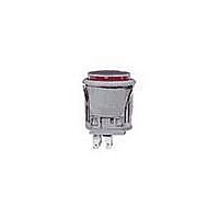
Manufacturer Part Number
LB16WKW01
Description
SW PB SPDT ALT RND SILV SLD MNT
Manufacturer
NKK Switches
Series
LBr
Type
Standardr
Specifications of LB16WKW01
Circuit
SPDT
Switch Function
On-On
Contact Rating @ Voltage
3A @ 125VAC
Actuator Type
Plunger for Cap
Mounting Type
Panel Mount
Termination Style
Solder, Quick Connect - .110" (2.8mm)
Contact Form
SPDT
Contact Rating
3 Amps at 125 Volts, 250 Volts
Actuator
Button, Round
Supply Voltage
125 Volts, 250 Volts
Mounting Style
Panel
Terminal Seal
Epoxy
Contact Plating
Silver
Contact Material
Phosphor Bronze
Illumination
Not Illuminated
Flammability Rating
UL 94 V-0
Body Length
21.5 mm
Body Shape
Round
Dielectric Strength
1000 Volts
Housing Material
Polyamide, Glass Fiber Reinforced
Insulation Resistance
200 MOhms
Mounting Angle
Vertical
Operating Force
5.39 N
Water / Moisture Rating
IP65
Body Style
Standard
Current, Rating
3 A
Electrical Life
100000 Operations
Force, Operating
5.39 N
Ip Rating
IP65
Material, Contact
Silver
Material, Terminal
Phosphor Bronze
Mechanical Life
1000000 Operations
Mounting Hole Size
0.866 "
Number Of Poles
1
Number Of Positions
2
Operation
On-On
Resistance, Contact
50 Milliohms
Resistance, Insulation
200 Megohms (Min.)
Special Features
Illuminated
Standards
UL Listed, File No. WOYR2.E44145, CSA Certified, File No. 023535-0-000
Temperature, Operating
-25 to +50 °C
Termination
Solder/Quick Connect
Voltage, Rating
250/30 VAC/VDC
Lead Free Status / RoHS Status
Lead free / RoHS Compliant
Illumination Type, Color
-
Illumination Voltage (nominal)
-
Lead Free Status / Rohs Status
Lead free / RoHS Compliant
Other names
LB16WKW01-RO
LB16WKW01-RO
LB16WKW01-RO


NKK Switches
Pole
Housing Colors Available:
Complete explanation of operating range in Supplement section.
DP
SP
W
AT607 & AT607N
W01
G01
T-1 Bi-pin
.866” (22.0mm)
Round
*LB16
*LB26
Model
LB15
LB25
* When in latchdown position for the alternate circuit, cap position is .039” (1.0mm) above the built-in bezel.
Silver Contacts
Gold Contacts
Normal
( ) = Momentary
INCANDESCENT & NEON LAMP CODES & SPECIFICATIONS
Plunger Position
ON
ON
ON
ON
Voltage
Current
Endurance
Ambient Temp. Range
AT607 Incandescent 5-volt or
12-volt; AT607N Neon 110-volt
Power Level
3A @ 125V AC & 250V AC
Logic Level
0.4VA max. @ 28V AC/DC max.
CONTACT MATERIALS, RATINGS & TERMINALS
Down
(ON)
(ON)
ON
ON
Avg.
Standard Size Panel Seal Pushbuttons
Hours
1-3 4-6
SHAPE & PANEL CUTOUT
Normal
Connected Terminals
K
V
1-3
I
POLES & CIRCUITS
Recommended Panel Thickness:
.039” ~ .157” (1.0mm ~ 4.0mm)
Recommended Panel Thickness with Splash Cover:
.039” ~ .138” (1.0mm ~ 3.5mm)
Overtightening the mounting nut AT074
may damage the switch housing.
115mA
5V AC
Black
05
HOUSING
–25°C ~ +50°C
1-2 4-5
7,000
Down
1-2
12V AC
60mA
12
Solder Lug/Quick Connect
Optional PCB adaptors AT711
& AT712 available; illustrated
in previous snap-in subsection.
Notes: Switch is marked with NC, NO, COM, L+, L–.
SPDT
DPDT
110V AC
10,000
1.5mA
01
Lamp circuit is isolated and requires
external power source.
Throw & Switch/Lamp Schematics
3
*
NC
1
G
COM
3
2
*
NO
NC
The electrical specifications shown are
determined at a basic temperature of
25°C. Lamp circuit is isolated and
requires external power source.
Recommended Resistors for Neon:
33K ohms for 110V AC;
100K ohms for 220V AC
1
Gray
COM
6
2
NO
NC
4
COM
5
Epoxy
Seal
NO
(2.0)
.079
Series LB
L (+)
L (+)
.047
(2.8)
.110
(1.2)
.067
(1.7)
.295
(7.5)
(22.0) Dia
.866
Thk = (0.5)
(10.5)
.413
(-) L
(-) L
.020
Related parts for LB16WKW01
Image
Part Number
Description
Manufacturer
Datasheet
Request
R

Part Number:
Description:
Rocker Switches & Paddle Switches High In-rush Rated Rocker Switch
Manufacturer:
NKK Switches
Datasheet:
Part Number:
Description:
Rocker Switches & Paddle Switches High In-rush Rated Rocker Switch
Manufacturer:
NKK Switches
Datasheet:
Part Number:
Description:
Rocker Switches & Paddle Switches High In-rush Rated Rocker Switch
Manufacturer:
NKK Switches
Datasheet:
Part Number:
Description:
Rocker Switches & Paddle Switches High In-rush Rated Rocker Switch
Manufacturer:
NKK Switches
Datasheet:

Part Number:
Description:
Pushbutton Switches SPST ON(OFF) 15/32'
Manufacturer:
NKK Switches
Datasheet:

Part Number:
Description:
Pushbutton Switches SPST OFF(ON) 15/32'
Manufacturer:
NKK Switches
Datasheet:

Part Number:
Description:
Pushbutton Switches ON(OFF) NORM CLSD 3A RED PLNGR LUG 15/32
Manufacturer:
NKK Switches
Datasheet:

Part Number:
Description:
Pushbutton Switches SPDT ON-(ON)
Manufacturer:
NKK Switches
Datasheet:

Part Number:
Description:
Pushbutton Switches ON-(ON) RND BUSH MNT RED LED RED/RED CAP
Manufacturer:
NKK Switches
Datasheet:
Part Number:
Description:
Pushbutton Switches SPST ON-(OFF) STRT
Manufacturer:
NKK Switches
Datasheet:
Part Number:
Description:
Pushbutton Switches OFF(ON) NORM OPEN 3A RED CAP LUG 15/32
Manufacturer:
NKK Switches
Datasheet:
Part Number:
Description:
Pushbutton Switches ILLUM PUSHBUTTON SPDT
Manufacturer:
NKK Switches
Datasheet:
Part Number:
Description:
Pushbutton Switches OFF(ON) NORM OPEN 3A BLK CAP LUG 15/32
Manufacturer:
NKK Switches
Datasheet:
Part Number:
Description:
Pushbutton Switches SPST NO Metric Thrd Blk Plunge w/Blu Cap
Manufacturer:
NKK Switches
Datasheet:
Part Number:
Description:
Pushbutton Switches SPST OFF-(ON) NO 3A
Manufacturer:
NKK Switches
Datasheet: