HS16-1N NKK Switches, HS16-1N Datasheet
HS16-1N
Specifications of HS16-1N
HS16-1N-RO
HS16-1N-RO


Related parts for HS16-1N


HS16-1N Summary of contents
Page 1
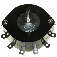
... HS, TS & PS Rotary Switches Download Specifications Configure This Switch! Standard Size Rotary Switches The HS, PS, TS Rotary Series standard size switches are available in low, medium, and high capacity models made of zinc plated steel mounting plate making them sturdy and dependable for high performance. Flat and knurled shafts are available as well as D flat shafts in two sizes ...
Page 2
... See Supplement section to find UL rating details. UL File No. WOYR2.E44145 Add “/U” to end of part number to order UL mark on switch. C-UL Recognized: HS16 models 1– through 6–pole are recognized at 12A @ 125V AC & 250V AC R See Supplement section to find C-UL rating details. UL File No. WOYR8.E44145 Add “/C-UL” to end of part number to order UL mark on switch. ...
Page 3
... Switch is viewed from shaft end and shown in position 1. Terminal numbers are not on switch. Standard Hardware shown on last page of this section. Keyway (4.8) Typ .189 (34.0) Dia 1.339 HS13X 12 AMP/SHORTING & NONSHORTING/30° INDEXING Knurled Shaft D-flat Shaft Nonshorting Shorting Nonshorting HS16-1 HS16-1S HS16-1N HS16-2 HS16-2S HS16-2N HS16-3 HS16-3S HS16-3N HS16-4 HS16-4S HS16-4N HS16-5 HS16-5S HS16-5N HS16-6 HS16-6S HS16-6N (65 ...
Page 4
... Dia .118 Maximum Effective Panel Thickness With Locking Ring .189” (4.8mm) Without Locking Ring .228” (5.8mm) TS5N NKK Switches Standard Size Rotaries Stopper Number of Shaft Settings Terminals Type COM, 11 LOAD D Flat COM, 22 LOAD D Flat ...
Page 5
... Panel Cutout (4.5) Dia Typ (10.5) Dia .177 .413 (9.0) .354 (3.0) Dia (20.0) R .118 .787 Maximum Effective Panel Thickness Without Locking Ring .189” (4.8mm) PS4N NKK Switches Standard Size Rotaries Stopper Number of Settings 2- COM, 11 LOAD 2- COM, 22 LOAD 2- COM, 33 LOAD 2- ...
Page 6
... M2.3 x 0.4 x 0.8 For HS16, TS, & PS Models The HS16, TS, and PS switches are supplied with the stopper plate set for the maximum number of positions allowed for that model. Prior to installation, the desired stopper setting should be made sure the shaft is turned counterclockwise to the extreme left. If the shaft is not turned counterclockwise to the extreme left, proper setting cannot be achieved ...