44D30-02-2-AJN Grayhill Inc, 44D30-02-2-AJN Datasheet - Page 8
44D30-02-2-AJN
Manufacturer Part Number
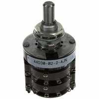
44D30-02-2-AJN
Description
SW ROTARY MIL DP 2DECK ADJ 6POS
Manufacturer
Grayhill Inc
Series
44r
Type
Rotaryr
Specifications of 44D30-02-2-AJN
Angle Of Throw
30°
Number Of Positions
2 ~ 6
Number Of Decks
2
Number Of Poles Per Deck
2
Circuit Per Deck
DP6T
Contact Rating @ Voltage
1A @ 115VAC
Actuator Type
Flatted (6.35mm dia)
Mounting Type
Panel Mount
Termination Style
Solder Lug
Orientation
Vertical
No. Of Poles
2
No. Of Switch Positions
6
Contact Current Ac Max
1A
Contact Current Dc Max
1A
Contact Voltage Ac Max
115V
Contact Voltage Dc Max
115V
Circuitry
DP6T
Brand/series
44 Series
Current, Rating
1 A
Dielectric Strength
1000 VAC
Material, Contact
Silver Alloy
Mechanical Life
100,000 Cycles
Number Of Poles
2
Termination
Solder
Voltage, Rating
115 V
Features Choice Include
shaft⁄panel seal, adjustable stops
Lead Free Status / RoHS Status
Lead free / RoHS Compliant
Lead Free Status / RoHS Status
Lead free / RoHS Compliant, Lead free / RoHS Compliant
Other names
44D30-02-2-AJN
GH7346
Q1410080
GH7346
Q1410080
Available stocks
Company
Part Number
Manufacturer
Quantity
Price
Company:

Part Number:
44D30-02-2-AJN
Manufacturer:
GHY
Quantity:
10


Grayhill, Inc. • 561 Hillgrove Avenue • LaGrange, Illinois
SPECIFICATIONS:
MIL-S-3786 Electrical Values
Military Style
Style M switches, at 85°C, approximately
68% humidity and sea level pressure and
style H and HS at 125°C have been tested to
make and break the following loads as stated
in MIL-DTL-3786/SR04; 250 milliamperes at
28 Vdc resistive, 100 milliamperes at 28 Vdc
inductive (2.8 henries); 75 milliamperes at
115 Vac resistive.
These switches have also been tested at
reduced barometric pressure (70,000 feet),
25°C at approximately 68% relative humidity
to make and break the following loads as
stated
milliamperes, 28 Vdc resistive; 25 milliamperes,
28 Vdc inductive (2.8 henries); 20
milliamperes, 115 Vac resistive. When tested
to these loads and conditions the style M, H
and HS switches meet the following life limiting
or failure criteria after 25,000 cycles in
accordance with MIL-S-3786.
Contact Resistance: 50 milliohms maximum
Insulation Resistance: 1,000 megaohms
minimum between terminals and shafts
Dielectric Strength: 1,000 Vac (atmospheric
pressure) and 450 Vac (reduced pressure)
minimum between mutually insulated parts.
When tested at sea level 25°C and 68%
relative humidity with failure criteria of 50
milliohms max. and 750 Vac breakdown
voltage, these switches will make and break
the following loads: 250 mA at 28 Vdc,
inductive (2.8 henries); 1.25 amps at 28 Vdc
resistive; 2.0 amps at 115 Vac, 60 Hz resistive,
for 10,000 cycles.
in
MIL-DTL-3786/SR04;
200
These switches also meet MIL-DTL-3786/SR04
for moisture resistance, medium and high shock,
vibration (10 to 2000 cps), thermal shock (-
65°C to 125°C), salt spray, explosion and
terminal pull.
Materials and Finishes
Standard Style
Bases: Melamine per (MIL-M-14) ASTM-D-
5948
Cover, Deck Separators, End Plate and Rotor
Mounting Plate: Phenolic per (MIL-M-14)
ASTM-D-5948
Mounting Bushings: Brass, tin/zinc-plated.
Shaft, Cover Plate, Retaining Rings, Through
Bolts, Shaft Extensions, Stop Arm, Thrust
Washers Stop Washers and Rear Support
Plate: Stainless Steel
Detent Balls: Steel, nickel-plated
Detent Springs: Tinned music wire
Rotor Contact, Stator (Base) Contacts: Silver
alloy
Terminals (Except Common): Brass, tin plated
Common Plate, Including Solder Lug: Brass,
silver-plated .0003" minimum
Mounting Hardware: Two mounting nuts .094"
(2,39) thick by .562" (14,27) across flats and
one internal tooth lockwasher are supplied
with each switch.
Stud Nuts, Mounting Nuts, Lock Washers:
Tin/zinc-plated or stainless steel.
Materials and Finishes
Military Qualified
Bases: Diallyl per (MIL-M-14) ASTM-D-5948
Cover, Deck Separators, End Plate and Rotor
Mounting Plate: Diallyl per (MIL-M-14) ASTM-
D-5948
60525-5997 • USA • Phone: 708-354-1040 • Fax: 708-354-2820 • www.grayhill.com
Multi-Deck Rotary Switches
Mounting Bushings: Brass, tin/zinc-plated.
Shaft, Cover Plate, Retaining Rings,
Through Bolts, Shaft Extensions, Stop
Arm, Stop Washers, Thrust Washers and
Rear Support Plate: Stainless steel
Detent Balls: Steel, nickel-plated
Detent Springs: Tinned music wire
Rotor Contact: Silver alloy
Terminals, Common Plate including
Solder Lug: Brass, silver-plated .0003"
minimum
Mounting Hardware: Two mounting nuts
.094" thick by .562" across flats and one
internal tooth lockwasher are supplied with
each switch.
Stud Nuts, Mounting Nuts, Lock Washers:
Tin/zinc-plated or stainless steel.
Additional Characteristics
Standard Style and Military Qualified
Contact: Shorting or non-shorting wiping
contacts with over 150 grams of contact
force
Rotational Torque: 8-115 ounce-inches
depending upon the number of poles per
deck, number of decks and angle of throw
Mechanical Life Expectancy: 100,000
cycles of operation
Shaft Flat Orientation: Flat opposite
contacting position of pole number one (See
circuit diagram).
Stop Strength: For Standard style: 15 pound-
inches minimum. For Adjustable stop styles:
12 pound-inches
Extended Stud: Single shaft switches of six
or more decks and concentric shaft switches
of a combination of five or more decks
(Standard style) or four or more decks (Military
style) have longer studs with extra mounting
nuts for recommended double end mount.
Rotary
29
Related parts for 44D30-02-2-AJN
Image
Part Number
Description
Manufacturer
Datasheet
Request
R

Part Number:
Description:
SW ROTARY MIL SP 2DECK ADJ 12POS
Manufacturer:
Grayhill Inc
Datasheet:

Part Number:
Description:
Rotary Switch, Standard, Adjustable Stops, 30°
Manufacturer:
Grayhill Inc
Datasheet:
Part Number:
Description:
Rotary Switch, Standard, Adjustable Stops, 30°
Manufacturer:
Grayhill Inc
Part Number:
Description:
Rotary Switch, Standard, Adjustable Stops, 30°
Manufacturer:
Grayhill Inc
Datasheet:
Part Number:
Description:
Rotary Switch, Standard, Adjustable Stops, 30°
Manufacturer:
Grayhill Inc

Part Number:
Description:
Rotary Switch, Standard, Adjustable Stops, 30°
Manufacturer:
Grayhill Inc
Datasheet:
Part Number:
Description:
Rotary Switch, Standard, Adjustable Stops, 30°
Manufacturer:
Grayhill Inc
Part Number:
Description:
44D30-01-4-AJS Table Stops, 30°
Manufacturer:
Grayhill Inc
Datasheet:
Part Number:
Description:
44D30-07-1-AJS Table Stops, 30°
Manufacturer:
Grayhill Inc
Datasheet:
Part Number:
Description:
44D30-10-1-AJS Table Stops, 30°
Manufacturer:
Grayhill Inc
Datasheet:
Part Number:
Description:
44D30-11-2-AJN Table Stops, 30°
Manufacturer:
Grayhill Inc
Datasheet:
Part Number:
Description:
Rotary Switch, Standard, Adjustable Stops, 30°
Manufacturer:
Grayhill Inc
Datasheet:
Part Number:
Description:
Rotary Switch, Standard, Adjustable Stops, 30°
Manufacturer:
Grayhill Inc