HS13X NKK Switches, HS13X Datasheet - Page 2
HS13X
Manufacturer Part Number
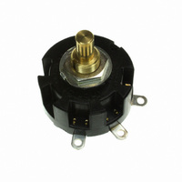
HS13X
Description
SW ROTARY SP 6A NON SHORT 2POS
Manufacturer
NKK Switches
Series
HSr
Type
Standard Size Rotariesr
Datasheet
1.AT432.pdf
(5 pages)
Specifications of HS13X
Number Of Positions
2
Number Of Decks
1
Number Of Poles Per Deck
1
Circuit Per Deck
SPDT
Contact Rating @ Voltage
6A @ 125VAC
Actuator Type
Round (6mm dia)
Mounting Type
Panel Mount
Termination Style
Solder Lug
Orientation
Vertical
Angle Of Throw
45°
Index Angle
45 deg
Contact Style
Non Shorting
Contact Material
Phosphor Bronze
Dielectric Strength
1500 VoltsAC
Voltage Rating
125 VoltsAC, 250 VoltsAC, 30 VoltsDC
Current Rating
6 Amps, 3 Amps, 5 Amps
Actuator
Shaft, Round
Contact Rating
6 Amps at 125 VoltsAC, 3 Amps at 250 VoltsAC, 5 Amps at 30 VoltsDC
Voltage Rating Ac
125 Volts, 250 Volts
Voltage Rating Dc
30 Volts
Total # Of Positions
2
Pole Throw Configuration
SP
Actuator Style
Shaft
Actuator Material
Brass
Current Rating (max)
6A
Illumination Type
Not Required
Ac Voltage Rating (max)
250VVAC
Dc Voltage Rating (max)
30VVDC
Mechanical Life
15000
Product Height (mm)
40mm
Operating Temp Range
-10C to 70C
Mounting Style
Panel
Terminal Type
Screw
Lead Free Status / RoHS Status
Lead free / RoHS Compliant
Other names
HS13X-RO
HS13X-RO
HS13X-RO


Standard Size Rotaries
Nonshorting
Switch is viewed from shaft end and shown in position 1. Terminal numbers are not on switch. Standard Hardware shown on last page of this section.
*
Switch is viewed from shaft end and shown in position 1. Terminal numbers are not on switch. Standard Hardware shown on last page of this section.
*
(4.8) Typ
.189
Maximum Effective Panel Thickness
HS13X
HS13Y
HS13Z
(65.0)
2.559
Round
Shaft
Wire harness & cable assemblies offered only in Americas.
HS16-1
HS16-2
HS16-3
HS16-4
HS16-5
HS16-6
Wire harness & cable assemblies offered only in Americas.
Keyway
Knurled Shaft
Without Locking Ring
With Locking Ring
(3.0) Dia
.118
(34.0) Dia
1.339
.189” (4.8mm)
.228” (5.8mm)
(10.5) Dia
.413
.354
(9.0)
HS13X-D
HS13Z-D
HS13Y-D
D-flat
Shaft
HS16-1S
HS16-2S
HS16-3S
HS16-4S
HS16-5S
HS16-6S
Shorting
(55.0)
2.165
Number of
.236
(6.0) Dia
Positions
M10 P0.75
.059
(10.3) Dia
.406
(1.5)
12 AMP/SHORTING & NONSHORTING/30° INDEXING
6 AMP SINGLE POLE/NONSHORTING/45° INDEXING
Nonshorting
2
3
4
HS16-1N
HS16-2N
HS16-3N
HS16-4N
HS16-5N
HS16-6N
(9.5)
.374
(10.0)
.394
(4.4)
.173
D-flat Shaft
(10.0)
.394
Stopper
Settings
(40.0)
1.575
Fixed
Fixed
Fixed
.236
• On each deck of multipole devices common and load terminals
• Switch is viewed from the shaft end and shown in position 1.
• Terminal numbers are on the switch bottom. Stopper positions
• Standard Hardware shown on last page of this section.
(6.0) Dia
(0.3)
.012
(16.0)
.630
are in the same positions as shown in the schematic above.
are molded on the top of the switch.
HS16-1SN
HS16-2SN
HS16-3SN
HS16-4SN
HS16-5SN
HS16-6SN
Shorting
M10 P0.75
Keyway
.028
(0.7) Typ
(10.0)
.394
(15.0)
1 COM, 2 LOAD
1 COM, 3 LOAD
1 COM, 4 LOAD
.224
.591
(5.7) Typ
Number of
Terminals
(14.0)
.551
Pole
1P
2P
3P
4P
5P
6P
COM
(24.5)
*
.965
4
Number of
(34.5)
1.358
Positions
(2.6) Dia Typ
.102
2-11
2-11
2-11
2-11
2-11
2-11
1, 2, 3, & 4
3
www.nkk.com
(44.5)
1.752
Terminals
1, 2, & 3
2.933
1
(74.5)
1 & 2
Load
2
(54.5)
2.146
2, 3, 4 . . . 11
2, 3, 4 . . . 11
2, 3, 4 . . . 11
2, 3, 4 . . . 11
2, 3, 4 . . . 11
2, 3, 4 . . . 11
(64.5)
2.539
Stopper
Settings
Maximum Effective Panel Thickness
HS13X
C 1
1
Without Locking Ring
2
With Locking Ring
(3.0) Dia
.118
.150” (3.8mm)
.189” (4.8mm)
(10.5) Dia
C L of Keyway
.413
(9.0)
.354
(0.84) Typ
.033
.276
(7.0) Max
1 COM, 11 LOAD
2 COM, 22 LOAD
3 COM, 33 LOAD
4 COM, 44 LOAD
5 COM, 55 LOAD
6 COM, 66 LOAD
Terminals
Number of
(2.6) Dia Typ
.102
HS16-2N
HS13Y
Schematics
*
.059
C 1
(10.3) Dia
.406
(1.5)
1
2
.374
(9.5)
C L of Keyway
Series HS
3
10
9
11
8
Schematic
C 1
7
(6.24) Typ
.246
HS13Z
HS13X
6
1
C 1
1
2
5
2
C L of Keyway
4
3
(8.0) Typ
.315
C L of Keyway
3
G47
4
G
Related parts for HS13X
Image
Part Number
Description
Manufacturer
Datasheet
Request
R

Part Number:
Description:
Rotary Switches 6 AMP 1 POLE 3 POS
Manufacturer:
NKK Switches
Datasheet:

Part Number:
Description:
SWITCH ROTARY SINGLE POLE 4POS
Manufacturer:
NKK Switches
Datasheet:

Part Number:
Description:
Rocker Switches & Paddle Switches High In-rush Rated Rocker Switch
Manufacturer:
NKK Switches
Datasheet:
Part Number:
Description:
Rocker Switches & Paddle Switches High In-rush Rated Rocker Switch
Manufacturer:
NKK Switches
Datasheet:
Part Number:
Description:
Rocker Switches & Paddle Switches High In-rush Rated Rocker Switch
Manufacturer:
NKK Switches
Datasheet:
Part Number:
Description:
Rocker Switches & Paddle Switches High In-rush Rated Rocker Switch
Manufacturer:
NKK Switches
Datasheet:

Part Number:
Description:
Pushbutton Switches SPST ON(OFF) 15/32'
Manufacturer:
NKK Switches
Datasheet:

Part Number:
Description:
Pushbutton Switches SPST OFF(ON) 15/32'
Manufacturer:
NKK Switches
Datasheet:

Part Number:
Description:
Pushbutton Switches ON(OFF) NORM CLSD 3A RED PLNGR LUG 15/32
Manufacturer:
NKK Switches
Datasheet:

Part Number:
Description:
Pushbutton Switches SPDT ON-(ON)
Manufacturer:
NKK Switches
Datasheet:

Part Number:
Description:
Pushbutton Switches ON-(ON) RND BUSH MNT RED LED RED/RED CAP
Manufacturer:
NKK Switches
Datasheet:
Part Number:
Description:
Pushbutton Switches SPST ON-(OFF) STRT
Manufacturer:
NKK Switches
Datasheet:
Part Number:
Description:
Pushbutton Switches OFF(ON) NORM OPEN 3A RED CAP LUG 15/32
Manufacturer:
NKK Switches
Datasheet:
Part Number:
Description:
Pushbutton Switches ILLUM PUSHBUTTON SPDT
Manufacturer:
NKK Switches
Datasheet:
Part Number:
Description:
Pushbutton Switches OFF(ON) NORM OPEN 3A BLK CAP LUG 15/32
Manufacturer:
NKK Switches
Datasheet: