A165S-T3M-2 Omron, A165S-T3M-2 Datasheet
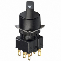
A165S-T3M-2
Specifications of A165S-T3M-2
Z1389


Related parts for A165S-T3M-2


A165S-T3M-2 Summary of contents
Page 1
... Refer to Safety Precautions for All Pushbutton Switches and Safety Precautions on page 15. List of Models Rectangular Solder A165@-J Series terminals Voltage- reduction A165@-J Series lighting Screw- less A165@-J Series clamp connector CSM_A165S_W_DS_E_4_1 Model Square A165@-A Series A165@-A Series A165@-A Series Round A165@-T Series A165@-T Series A165@-T Series 1 ...
Page 2
... Manual R Red Automatic G Green Y Yellow Manual Voltage Reduction Unit (24-V Built-in LED) Automatic Symbol Type T1 T2 Note: 1. Solder terminals are only available with 100-V models. A165S/W (6) Contact Configuration Symbol Type Terminal 1 SPDT Solder terminal 2 DPDT 1P SPDT PCB terminal 2P DPDT 2S ...
Page 3
... LED A165W-A2M@-24D-2 Non-lighted A165S-A2M-2 LED A165W-A2A@-24D-2 Non-lighted A165S-A2A-2 LED A165W-A3M@-24D-2 Non-lighted A165S-A3M-2 Model LED A165W-T2M@-24D-1 Non-lighted A165S-T2M-1 LED A165W-T2A@-24D-1 Non-lighted A165S-T2A-1 LED A165W-T2M@-24D-2 Non-lighted A165S-T2M-2 LED A165W-T2A@-24D-2 Non-lighted A165S-T2A-2 LED A165W-T3M@-24D-2 Non-lighted A165S-T3M-2 3 ...
Page 4
... Note: Temperature rises in incandescent lamps can cause heat deformation. Solder terminals (no transformer) Lighted/non-lighted Selector (Listed on Page 5.) Square Models Non-lighted Models Switch (Listed on Page 7.) PCB terminals Lighted/non-lighted Note: Socket Unit Sets that combine a Lamp and a Socket Unit are also available. A165S/W Round Models 4 ...
Page 5
... A165S-J3A A165W-A2M@ A165S-A2M Enter the desired color A165W-A2A@ symbol for the Selec- A165S-A2A tor (red), A165W-A3M@ Y (yellow), A165S-A3M G (green) A165W-A3A@ A165S-A3A A165W-T2M@ A165S-T2M Enter the desired color A165W-T2A@ symbol for the Selec- A165S-T2A tor (red), A165W-T3M@ Y (yellow), A165S-T3M G (green) A165W-T3A@ A165S-T3A 5 ...
Page 6
... Square Models Socket Unit Set with Screw-less Clamp Connectors Classification SPDT DPDT 24 V DPDT Classification 2 notches SPDT 2 notches DPDT 3 notches A165S/W Round Models Lighted/Non-lighted Models Lamp Lighted/ Non-lighted Models Note: Non-lighted models do not include a Lamp. Model A16W-2N@-24D-1 A16W-2N@-24D-2 Solder terminals ...
Page 7
... Selector Switch Selector Switch Yes Yes Yes Yes Yes Yes ■ Specifications and dimensions: Refer to pages 8 to 10. ■ Accessories, replacements, and tools: Refer to this page A165S/W Model Remarks A16-2S Used for Pushbutton A16L-∆-@-2S Switches and Knob-type Selector A16L-∆-T1-2S Switches. ...
Page 8
... N strength Length of exposed wire Compliant JIS C 2811 Terminal Blocks for Industrial Use standards Operating Characteristics Type Characteristics Operating force (OF) max. Set position (SP) A165S/W CCC (GB14048. 125 VAC 250 VAC VDC Contact form NC COM NO Internal limiting resistor Red, yellow: 300 Ω ...
Page 9
... Non-lighted models ●Number of Notches and Reset Method · 2 Notches: Manual reset, Automatic reset · 3 Notches: Manual reset, Automatic reset Switch ●Switch Specifications 125 VAC 250 VAC VDC Minimum applicable load VDC FP 90° A165S/W SW2 SW1 9 ...
Page 10
... The lamp terminal is not provided with non-lighted models. 9.5 18 Packing (t0.5) 9 Packing (t0.5) 9 Packing (t0.5) A165S/W (Unit M16×1 18 12.2 4 Lamp terminal 10.8 21.1 28.5 4.85 12.4 15.8 Model, standard, lot No., serial number Mounting nut Lock ring M16×1 12.2 18 ...
Page 11
... Mounting nut Switch (22.4) 20.6 2.8 12.4 48.9 18.5 10.8 9 M16×1 Lock ring Mounting nut (31.7) 27.4 Packing (t0.5) A165S/W (Unit: mm) M16×1 18.4 20.4 6.3 0.5 4 10.8 9.5 21.1 18.5 28.3 4.85 12.4 18.6 0.5 Mounting nut Packing (t0.5) ...
Page 12
... NO 2.6 0.9 COM SW1 1.5 Lamp terminal 2.8 Dimensions of Terminal Holes 2.6 NC 0.9 NO 1.5 COM 2.8 SW1 A165S/W (Unit: mm) Square A165@-A, Round A165@-T (Top View) +0.2 16 dia. 19 min. 0 (25 min.) 19 min. (33 min.) Square A165@-A, Round A165@-T (Top View) +0.2 16 dia min. ...
Page 13
... min.: Rectangular min.: Square/Round min. Use t = 1.6 for the PCB. Note: Secure the panel to the board using stud bolts if force will be applied to the board after wiring. A165S/W (Unit: mm) Lighted DPDT Switches Terminal Arrangement (Bottom View) Side with TOP indicated ...
Page 14
... Note: Secure the panel to the board using stud bolts if force will be applied to the board after wiring. A165 Key-type Selector Switch Fix the Switch screw and rotate the flange in 45° turns. Flange Lock ring Switch screw A165S/W (Unit: mm) Terminal Arrangement (Bottom View) Side with TOP indicated NC NC ...
Page 15
... LED • The LED current-limiting resistor is built-in, so external resistance is not required. Rated voltage Internal limiting resistor Red, yellow: 300 Ω 5 VDC Green: 160 Ω Red, yellow: 1 kΩ 12 VAC/VDC Green: 910 Ω 24 VAC/VDC 2.4 kΩ A165S/W 100 1,000 Current (mA) 15 ...
Page 16
... When handling the Switches, do not throw or drop them. Do not allow the Switch to drop and hit the ground. Do not place or drop heavy objects on the Switch. Do not operate the Switch with hard or sharp objects. Hammer Screwdriver A165S/W 16 ...
Page 17
... Please read and understand this catalog before purchasing the products. Please consult your OMRON representative if you have any questions or comments. WARRANTY OMRON's exclusive warranty is that the products are free from defects in materials and workmanship for a period of one year (or other period if specified) from date of sale by OMRON. OMRON MAKES NO WARRANTY OR REPRESENTATION, EXPRESS OR IMPLIED, REGARDING NON-INFRINGEMENT, MERCHANTABILITY, OR FITNESS FOR PARTICULAR PURPOSE OF THE PRODUCTS ...