A165W-A3MY-24D-2 Omron, A165W-A3MY-24D-2 Datasheet - Page 12
A165W-A3MY-24D-2
Manufacturer Part Number
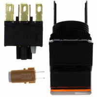
A165W-A3MY-24D-2
Description
SWITCH KNOB SQ 3-POS DPDT ILL
Manufacturer
Omron
Series
A165Wr
Type
Standardr
Specifications of A165W-A3MY-24D-2
Circuit
DPDT
Switch Function
3 Position, Maintained
Contact Rating @ Voltage
5A @ 125VAC
Illumination
Illuminated
Illumination Type, Color
LED, Yellow
Illumination Voltage (nominal)
24 VDC
Mounting Type
Panel Mount
Termination Style
Quick Connect - .110" (2.8mm)
Panel Cutout Dimensions
16mm (Round)
Body Shape
Flange
Control Type
Knob-Type Selector
Contact Form
DPDT
Contact Rating
10 mAmps
Flange Shape
Square
Illuminated
Y
Lens Color
Yellow
Lead Free Status / RoHS Status
Lead free / RoHS Compliant
Lead Free Status / RoHS Status
Lead free / RoHS Compliant, Lead free / RoHS Compliant
Other names
A165WA3MY24D2
Z1374
Z1374


Dimensions
Panel Cutouts
Models with Solder Terminals and Models with Screw-less Clamp Connectors
Models with PCB Terminals
Terminal Arrangement
Models with Solder Terminals without Reduced-voltage Lighting (Lamp terminals are not provided with the Non-lighted
Knob-type Selector Switches and Key-type Selector Switches.)
Note: 1. Make sure the thickness of the mounting panel is 0.5 to 3.2 mm.
Note: 1. Ensure that the variation in the distance between the centers of neighboring mounting holes is less than ±0.1 mm.
Dimensions of
Terminal Holes
1.5
2.8
Dimensions of
Terminal Holes
1.5
2.8
2. If the panel is to be finished with coating, etc., make sure that the panel meets the specified dimensions after coating.
3. Figures in parentheses are for screw-less clamp connectors.
2. Make sure the thickness of the mounting panel is 0.5 to 3.2 mm. If, however, a Switch Guard or Dust Cover is used, the thickness of the mounting panel must
3. If the panel is to be finished with coating, etc., make sure that the panel meets the specified dimensions after coating.
be 0.5 to 2 mm.
Lamp terminal
2.6
0.9
2.6
0.9
7.4
7.4
9.1 ± 0.05
Non-lighted SPDT Switches
14.7 ± 0.05 dia.
16
Lighted SPDT Switches
+0.2
0
Rectangular A165@-J
Rectangular A165@-J
dia.
16
+0.2
0
(Top View)
5.1 ± 0.05
dia.
12.2
12.2
18
18
(25 min.)
24 min.
(Top View)
24 min.
Terminal Arrangement
(Bottom View)
Note: The L+ is not shown
on the Switch.
Terminal Arrangement
(Bottom View)
Side with TOP
indicated
(33 min.)
19 min.
24 min.
COM
SW1
COM
SW1
NC
NO
NC
NO
L-
Dimensions of
Terminal Holes
Dimensions of
Terminal Holes
1.5
2.8
1.5
2.8
Lamp terminal
2.6
0.9
2.6
0.9
7.4
7.4
Square A165@-A, Round A165@-T
Square A165@-A, Round A165@-T
Non-lighted DPDT Switches
9.1 ± 0.05
Lighted DPDT Switches
14.7 ± 0.05 dia.
16
+0.2
0
12.2
12.2
dia.
16
18
18
+0.2
(Top View)
0
dia.
5.1 ± 0.05
(25 min.)
19 min.
(Top View)
24 min.
Terminal Arrangement
(Bottom View)
Note: The L+ is not shown
on the Switch.
(33 min.)
19 min.
Terminal Arrangement
(Bottom View)
Side with TOP
indicated
24 min.
A165S/W
COM
SW1
COM
SW1
NC
NO
NC
NO
L-
(Unit: mm)
COM
SW2
COM
SW2
NC
NO
NC
NO
12
Related parts for A165W-A3MY-24D-2
Image
Part Number
Description
Manufacturer
Datasheet
Request
R

Part Number:
Description:
SWITCH UNIT SQUARE ALT 3POS YEL
Manufacturer:
Omron
Datasheet:

Part Number:
Description:
G6S-2GLow Signal Relay
Manufacturer:
Omron Corporation
Datasheet:
Part Number:
Description:
Compact, Low-cost, SSR Switching 5 to 20 A
Manufacturer:
Omron Corporation
Datasheet:
Part Number:
Description:
Manufacturer:
Omron Corporation
Datasheet:
Part Number:
Description:
Manufacturer:
Omron Corporation
Datasheet:
Part Number:
Description:
Manufacturer:
Omron Corporation
Datasheet:
Part Number:
Description:
Manufacturer:
Omron Corporation
Datasheet:
Part Number:
Description:
Manufacturer:
Omron Corporation
Datasheet:
Part Number:
Description:
Manufacturer:
Omron Corporation
Datasheet: