SS-01GLP Omron, SS-01GLP Datasheet - Page 5
SS-01GLP
Manufacturer Part Number
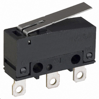
SS-01GLP
Description
SWITCH LEVER SPDT .1A SLDR
Manufacturer
Omron
Series
SSr
Type
Basic Switchesr
Specifications of SS-01GLP
Circuit
SPDT
Switch Function
On-Mom
Contact Rating @ Voltage
0.1A @ 30VDC
Actuator Type
Lever, Straight
Mounting Type
Chassis Mount
Termination Style
Solder Lug
Operating Force
50gf
Contact Form
SPDT
Contact Rating
0.1 Amp at 125 Volts, 0.1 Amp at 30 Volts
Actuator
Lever, Hinge
Post Position
Straight Vertical
Microswitch Type
Subminiature
Actuator Style
Hinge Lever
Operating Force Max
51gf
Contact Voltage Ac Nom
125V
Contact Voltage Dc Nom
30V
Contact Current Max
100mA
Body Style
Subminiature
Current, Rating
0.1 A
Dielectric Strength
1500 VAC
Ip Rating
IP40
Mounting Hole Size
1.6 mm
Number Of Poles
1
Operation
Snap Action
Termination
Solder
Voltage, Rating
30 VDC
Lead Free Status / RoHS Status
Lead free / RoHS Compliant
Lead Free Status / RoHS Status
Lead free / RoHS Compliant, Lead free / RoHS Compliant
Other names
SS01GLP
SW776
SW776


Precautions
■ Correct Use
Mounting
Mount the Switch onto a flat surface. Mounting on an uneven surface
may cause deformation of the Switch, resulting in faulty operation or
breakage in the housing.
Operating Stroke Setting
Take particular care in setting the operating stroke for the pin plunger
models. Make sure that the operating stroke is 60% to 90% of the
rated OT distance. Do not operate the actuator exceeding the OT dis-
tance, otherwise the life expectancy of the Switch may be shortened.
Using Microloads
Using a model for ordinary loads to switch microloads may result in
faulty operation. Instead, use the models that are designed for micro-
loads and that operate in the following range;
However, even when using microload models within the operating
range shown above, if inrush current or inductive voltage spikes
occur when the contact is opened or closed, it may increase contact
wear and so decrease the service life. Therefore, insert a contact
protection circuit where necessary.
30
24
12
5
0
0.1
0.16 mA
Inoperable
range
1 mA
1
Operating range
for micro load
models SS-01P
10
26 mA
100 mA 160 mA
100 mA
100
Operating
range for
general-
load models
SS-3P
Current (mA)
1,000
■ Cautions
Handling
Turn OFF the power supply before mounting or removing the Switch,
wiring, or performing maintenance or inspection. Failure to do so may
result in electric shock or burning.
Solder Terminal Connection
When soldering lead wires to solder terminals, first insert the lead
wire conductor through the terminal hole and then solder.
Make sure that the temperature at the tip of the soldering iron is
350 to 400°C. Do not take more than 3 seconds to solder the switch
terminal, and do not impose external force on the terminal for 1 min
after soldering. Improper soldering involving an excessively high
temperature or excessive soldering time may deteriorate the charac-
teristics of the Switch.
Quick-Connect Terminals
Wire quick-connect terminals (#110) with receptacles. Insert the ter-
minals straight into the receptacles. Do not impose excessive force
on the terminal in the horizontal direction, otherwise the terminal may
be deformed or the housing may be damaged.
Use appropriate #110 QC connectors, made by Nippon Tanshi or
Tyco Electronics, to mate with the quick-connect versions of the
switch. These connectors are not sold by OMRON. Contact Nippon
Tanshi or Tyco Electronics to purchase these connectors.
PCB Terminal Connection
When using automatic soldering baths, we recommend soldering at
260±5°C within 5 seconds. Make sure that the liquid surface of the
solder does not flow over the edge of the board.
When soldering by hand, as a guideline, solder with a soldering iron
with a tip temperature of 350 to 400°C within 3 seconds, and do not
apply any external force for at least 1 minutes after soldering. When
applying solder, keep the solder away from the case of the Switch
and do not allow solder or flux to enter the case.
Insulation Distance
Use a separator between the switch and metal mounting panels, to
ensure proper dielectric characteristics are achieved.
Subminiature Basic Switch
SS-P
107
Related parts for SS-01GLP
Image
Part Number
Description
Manufacturer
Datasheet
Request
R

Part Number:
Description:
SWITCH BASIC SPDT .1A 150GF SLD
Manufacturer:
Omron
Datasheet:

Part Number:
Description:
SUBMINIATURE BASIC SWITCH
Manufacturer:
Omron
Datasheet:

Part Number:
Description:
PIN PLUNGER SPDT 1.8OZ/.1AMP
Manufacturer:
Omron
Datasheet:

Part Number:
Description:
SW SUBMINI SPDT .1A PIN PLNGR
Manufacturer:
Omron
Datasheet:
Part Number:
Description:
SW SUBMINI SPST-NO .1A PIN PLNGR
Manufacturer:
Omron
Datasheet:
Part Number:
Description:
SUBMINIATURE BASIC SWITCH
Manufacturer:
Omron
Datasheet:
Part Number:
Description:
Subminiature Basic Switch
Manufacturer:
Omron
Datasheet:
Part Number:
Description:
SUBMINIATURE BASIC SWITCH
Manufacturer:
Omron
Datasheet:
Part Number:
Description:
SUBMINIATURE BASIC SWITCH
Manufacturer:
Omron
Datasheet:
Part Number:
Description:
Subminiature Basic Switch
Manufacturer:
Omron
Datasheet:
Part Number:
Description:
SUBMINIATURE BASIC SWITCH
Manufacturer:
Omron
Datasheet:
Part Number:
Description:
SUBMINIATURE BASIC SWITCH
Manufacturer:
Omron
Datasheet:
Part Number:
Description:
SUBMINIATURE BASIC SWITCH
Manufacturer:
Omron
Datasheet:
Part Number:
Description:
SUBMINIATURE BASIC SWITCH
Manufacturer:
Omron
Datasheet:
Part Number:
Description:
Basic / Snap Action / Limit Switches HINGE LEVER SOLDER SNAP-ACTION
Manufacturer:
Omron