D2F-FL Omron, D2F-FL Datasheet - Page 6
D2F-FL
Manufacturer Part Number
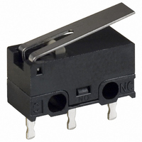
D2F-FL
Description
LEVER SWITCH PCB SPDT 1A 25GF
Manufacturer
Omron
Series
D2Fr
Type
Snap Actionr
Specifications of D2F-FL
Circuit
SPDT
Switch Function
On-Mom
Contact Rating @ Voltage
1A @ 125VAC
Actuator Type
Lever, Straight
Mounting Type
Through Hole
Termination Style
PC Pin
Operating Force
25gf
Contact Form
SPDT
Contact Rating
1 Amp at 125 Volts, 0.5 Amp at 30 Volts
Actuator
Lever, Hinge
Microswitch Type
Ultra Subminiature
Actuator Style
Hinge Lever
Operating Force Max
25gf
Contact Voltage Ac Nom
125V
Contact Voltage Dc Nom
30V
Contact Current Max
1A
Body Style
Ultra Subminiature
Brand/series
D2F Series
Current, Rating
1/0.5 AAC/ADC
Dielectric Strength
1500 VAC
Mounting Hole Size
1.2 mm
Number Of Poles
1
Operation
Snap Action
Standards
UL Listed, CSA Certified
Temperature, Operating
-25 to +65 °C with No Icing
Termination
Through Hole
Voltage, Rating
125/30 VAC/VDC
Lead Free Status / RoHS Status
Lead free / RoHS Compliant
Lead Free Status / RoHS Status
Lead free / RoHS Compliant, Lead free / RoHS Compliant
Other names
D2FFL
SW153
SW153
Available stocks
Company
Part Number
Manufacturer
Quantity
Price
Company:

Part Number:
D2F-FL-D
Manufacturer:
OMRON
Quantity:
12 000
Part Number:
D2F-FL3-D
Manufacturer:
OMRON/欧姆龙
Quantity:
20 000


D2F
Precautions
Refer to General Information.
■
Terminal Connection
When soldering a lead wire to the terminal, first insert the lead
wire conductor into the terminal hole and then perform soldering.
Make sure that the capacity of the soldering iron is 30 W maxi-
mum and that the temperature of the soldering iron tip is approxi-
mately 300°C. (350°C maximum.) Complete the soldering within
3 s.
Using a switch with improper soldering may result in abnormal
heating, possibly resulting in burn.
Applying a soldering iron for more than 3 s or using one that is
rated at more than 30 W may deteriorate the switch characteris-
tics.
When using automatic soldering baths, we recommend soldering
at 260±5°C within 5 seconds. Make sure that the liquid surface of
the solder does not flow over the edge of the board.
■
Mounting
Turn OFF the power supply before mounting or removing the
Switch, wiring, or performing maintenance or inspection. Failure
to do so may result in electric shock or burning.
Use M2 mounting screws with plane washers or spring washers
to securely mount the Switch. Tighten the screws to a torque of
0.08 to 0.1 N·m {0.8 to 1 kgf·cm}.
Mount the Switch onto a flat surface. Mounting on an uneven sur-
face may cause deformation of the Switch, resulting in faulty oper-
ation or breakage in the housing.
6
Cat. No. B036-E1-08
Simulated Roller Lever Models (R2.5)
D2F-L30@
D2F-01L30@
D2F-FL30@
D2F-01FL30@
Cautions
Correct Use
ALL DIMENSIONS SHOWN ARE IN MILLIMETERS.
To convert millimeters into inches, multiply by 0.03937. To convert grams into ounces, multiply by 0.03527.
12.7
3.3
R2.5
Note: Stainless-steel lever
OP
A
FP
Using Micro Loads
Using a model for ordinary loads to open or close the contact of a
micro load circuit may result in faulty contact. Use models that
operate in the following range. However, even when using micro
load models within the operating range shown below, if inrush
current occurs when the contact is opened or closed, it may
increase contact wear and so decrease durability. Therefore,
insert a contact protection circuit where necessary.
The minimum applicable load is the N-level reference value. This
value indicates the malfunction reference level for the reliability
level of 60% (λ 60). The equation, λ 60 = 0.5×10
indicates that the estimated malfunction rate is less than 1/
2,000,000 operations with a reliability level of 60%.
5.7
t=0.3 (see note)
3
Inoperable
range
OF max.
RF min.
OT min.
MD max.
FP max.
OP
Model
Operating range
for micro load
models D2F-01
0.54 N {55 gf}
0.04 N {4 gf}
0.5 mm
0.5 mm
12.6 mm
9.5±1.0 mm
D2F-01L30@
D2F-L30@
Current (mA)
Operating
range for
general-load
models
D2F
0.3 N {31 gf}
0.02 N {2 gf}
D2F-01FL30@
D2F-FL30@
–6
/operations
D2F
Related parts for D2F-FL
Image
Part Number
Description
Manufacturer
Datasheet
Request
R

Part Number:
Description:
Subminiature Basic Switch
Manufacturer:
Omron
Datasheet:
Part Number:
Description:
SUBMINIATURE BASIC SWITCH
Manufacturer:
Omron
Datasheet:
Part Number:
Description:
SUBMINIATURE BASIC SWITCH
Manufacturer:
Omron
Datasheet:

Part Number:
Description:
SUBMINIATURE BASIC SWITCH
Manufacturer:
Omron
Datasheet:
Part Number:
Description:
Switch, SubMiniature, Snap Action, PIN PLUNGER, PCB Terminal, Standard LOAD Actuator
Manufacturer:
Omron
Datasheet:

Part Number:
Description:
LEVER SWITCH PCB SPDT .1A 80GF
Manufacturer:
Omron
Datasheet:

Part Number:
Description:
SWITCH BASIC SPDT .1A 80GF PCB
Manufacturer:
Omron
Datasheet:

Part Number:
Description:
SWITCH BASIC SPDT 3A 80GF PCB
Manufacturer:
Omron
Datasheet:
Part Number:
Description:
SWITCH BASIC SPDT .1A 25GF PCB
Manufacturer:
Omron
Datasheet:

Part Number:
Description:
SWITCH BASIC SPDT 3A 80GF PC MT
Manufacturer:
Omron
Datasheet:

Part Number:
Description:
SUBMINIATURE BASIC SWITCH
Manufacturer:
Omron
Datasheet:

Part Number:
Description:
SUBMINIATURE BASIC SWITCH
Manufacturer:
Omron
Datasheet:

Part Number:
Description:
SUBMINIATURE BASIC SWITCH
Manufacturer:
Omron
Datasheet:

Part Number:
Description:
SWITCH BASIC SPDT 3A 80GF
Manufacturer:
Omron
Datasheet:
Part Number:
Description:
SWITCH LEVER SPDT .1A 25GF
Manufacturer:
Omron
Datasheet: