V-15G5-1C26-K Omron, V-15G5-1C26-K Datasheet - Page 22
V-15G5-1C26-K
Manufacturer Part Number
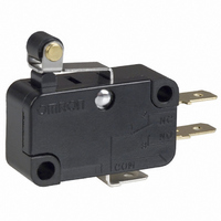
V-15G5-1C26-K
Description
SWITCH ROLLER SPDT 15A .187QC
Manufacturer
Omron
Series
Vr
Type
Snap Actionr
Specifications of V-15G5-1C26-K
Circuit
SPDT
Switch Function
On-Mom
Contact Rating @ Voltage
15A @ 250VAC
Actuator Type
Lever, Roller
Mounting Type
Chassis Mount
Termination Style
Quick Connect - .187" (4.7mm)
Operating Force
480gf
Contact Form
SPDT
Contact Rating
15 Amps at 250 Volts
Actuator
Hinge Roller Lever
Microswitch Type
Snap Action
Actuator Style
Hinge Roller Lever
Operating Force Max
400gf
Contact Voltage Ac Nom
250V
Contact Voltage Dc Nom
250V
Contact Current Max
15A
Lead Free Status / RoHS Status
Lead free / RoHS Compliant
Lead Free Status / RoHS Status
Lead free / RoHS Compliant, Lead free / RoHS Compliant
Other names
SW136
V15G51C26K
V15G51C26K


General Information
Switch Trouble and Corrective Action
Failures
related to
electrical
characteristics
characteristics
Failures
related to
mechanical
characteristics
h
l t d t
Type
t i ti
Contact
Actuator
Mounting
section
sec o
Terminal
of failure
Location
Contact
f il
failure
Malfunction
Contact
welding
Insulation
degradation
deg ada o
(b
(burning)
Operating
failure
Low
d
durability
Damage
Damage
Damage
Failure
bilit
i
)
Dust and dirt on the contacts.
Water or other liquid has penetrated into a
switch.
Chemical substances have been generated
on the contact surface due to the
atmosphere containing chemical corrosive
gas.
Chemical substances have been generated
on the contact surface when the switch
switches a very low load.
Solder flux has penetrated into the switch.
Silicon gas exists near the switch.
The contacts are separated from each other
by vibration or shock.
The load connected to the switch is too high. Switch the load with a high-capacity relay
Contacts have been melted and scattered
by arc.
Water has penetrated into the switch
because the switch has been used in an
extremely hot environment.
Liquid has penetrated into the switch and
been carbonized by arc heat.
The sliding part of the actuator has been
damaged because an excessive force was
applied on the actuator.
Foreign material like dust, dirt and oil has
penetrated into the switch.
The actuator does not release because the
operating body is too heavy.
The switch is loosely installed and thus does
not operate even when the actuator is at the
rated OP.
The shape of the dog or cam is improper.
The operating method is improper.
The operating speed is too high.
A shock has been applied to the actuator.
The caulked part is not good enough or the
assembled condition is poor.
Deformation or drop-out
Actuator was subjected to an excessive
force and force from an inappropriate
direction.
Screws have not been inserted straight.
The mounting screws were tightened with
too much torque.
The mounting pitch is wrong.
The switch is not installed on a flat surface.
An excessive force was applied to the
terminal while being wired.
The plastic part has been deformed by
soldering heat.
Possible cause
Remove the cause of the problem, place
th
the switch in a box, or use a sealed
switch.
Use a switch having contacts with high
environmental resistivity (such as gold or
alloy contacts).
Review the soldering method or use a
sealed or flux-tight switch.
Remove the material generating gas, or
adjust contact capacity to prevent
formation of silicon compounds on the
contacts.
Use a switch having a high contact force
(generally a high OF).
or magnetic relay or insert a contact
protection circuit.
Switch the load with a high-capacity relay
or magnetic relay.
Remove the cause of the problem, place
the switch in a box, or use a sealed
switch.
Make sure that no excessive force is
applied to the actuator, or use an auxiliary
actuator mechanically strong.
Remove the cause of the problem or place
the switch in a box.
Use a switch having a higher OF.
Secure the switch.
Change the design of the dog or cam.
Review the operating stroke and operating
speed.
Remove the cause of problem or use a
switch mechanically strong.
Replace the switch with a new one.
Review the handling and operating
method.
Check and correct screw insertion
method.
Tighten the screws with an appropriate
torque.
Correct the pitch.
Install the switch on a flat surface.
Do not apply an excessive force.
Reduce the soldering time or soldering
temperature. (Refer to the information
given under Precautions for that model.)
it h i
General Information
Corrective action
b
p
l d
, p
31
Related parts for V-15G5-1C26-K
Image
Part Number
Description
Manufacturer
Datasheet
Request
R

Part Number:
Description:
SWITCH ROLLER SPDT 15A .187QC
Manufacturer:
Omron
Datasheet:

Part Number:
Description:
MINIATURE BASIC SWITCH
Manufacturer:
Omron
Datasheet:

Part Number:
Description:
MINIATURE BASIC SWITCH
Manufacturer:
Omron
Datasheet:

Part Number:
Description:
MINIATURE BASIC SWITCH
Manufacturer:
Omron
Datasheet:

Part Number:
Description:
MINIATURE BASIC SWITCH
Manufacturer:
Omron
Datasheet:
Part Number:
Description:
MINIATURE BASIC SWITCH
Manufacturer:
Omron
Datasheet:

Part Number:
Description:
MICRO SWITCH, PIN PLUNGER, SPDT 15A 250V
Manufacturer:
Omron
Datasheet:

Part Number:
Description:
SWITCH BASIC SPDT 15A 200GF
Manufacturer:
Omron
Datasheet:
Part Number:
Description:
SWITCH BASIC SPST 15A .187QC
Manufacturer:
Omron
Datasheet:
Part Number:
Description:
SWITCH BASIC SPDT 15A 400GF
Manufacturer:
Omron
Datasheet:
Part Number:
Description:
SWTCH MINI SPST-NC 15A PIN PLNGR
Manufacturer:
Omron
Datasheet:
Part Number:
Description:
MINIATURE BASIC SWITCH
Manufacturer:
Omron
Datasheet:
Part Number:
Description:
MINIATURE BASIC SWITCH
Manufacturer:
Omron
Datasheet: