D2SW-3L3HS Omron, D2SW-3L3HS Datasheet - Page 3
D2SW-3L3HS
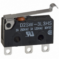
Manufacturer Part Number
D2SW-3L3HS
Description
SWITCH 3A LEVER SEALED SLD TERM
Manufacturer
Omron
Series
D2SWr
Type
Snap Actionr
Specifications of D2SW-3L3HS
Circuit
SPDT
Switch Function
On-Mom
Contact Rating @ Voltage
3A @ 125VAC
Actuator Type
Lever, Simulated Roller
Mounting Type
Chassis Mount
Termination Style
Solder Lug
Operating Force
60gf
Contact Form
SPDT
Contact Rating
3 Amps at 125 Volts, 3 Amps at 30 Volts
Actuator
Lever, Simulated Roller
Microswitch Type
Miniature
Actuator Style
Simulated Roller Lever
Operating Force Max
60gf
Contact Voltage Ac Nom
250V
Contact Voltage Dc Nom
30V
Contact Current Max
3A
Body Style
Subminiature
Brand/series
D2SW Series
Current, Rating
3 A
Dielectric Strength
1500 VAC
Ip Rating
IP50
Mounting Hole Size
2.4 mm
Number Of Poles
1
Operation
Snap Action
Standards
UL Recognized, CSA Certified
Temperature Rating
-40 to +85 °C
Termination
Solder
Voltage, Rating
125/30 VAC/VDC
Contacts
SPDT, 3 A @ 125 VAC
Lead Free Status / RoHS Status
Lead free / RoHS Compliant
Lead Free Status / RoHS Status
Lead free / RoHS Compliant, Lead free / RoHS Compliant
Other names
D2SW-3L3H
D2SW3L3HS
SW296
D2SW3L3HS
SW296


■ Approvals
Consult your OMRON sales representative for specific models with
standard approvals.
UL Recognized, CSA Certified
EN 61058-1 (VDE Approval)
Testing conditions: 5E4 (50,000 operations), T85 (0°C to 85°C)
Engineering data
■ Mounting
All switches may be panel mounted using M2.3 mounting screws with
plane washers or spring washers to securely mount the switch.
Tighten the screws to a torque of 0.23 to 0.26 N·m.
■ Structure
125 VAC
Rated Voltage
125 VAC
250 VAC
30 VDC
Rated Voltage
*Indicates the color of the lead wire.
SPDT
COM
(Black*)
Panel Mounting
Two, 2.4-dia. mounting hole or M2.3 screw hole
NO
(Blue*)
NC
(Red*)
D2SW-3
0.1 A
9.5
3 A
2 A
3 A
D2SW-01
D2SW-01
0.1 A
0.1 A
- - -
SPST-NC
COM
(Black)
NC
(Red)
■ Contact Specifications
Note: Minimum applicable loads are indicated by N standard refer-
■ PCB Layout
Specification
Material
Gap (standard value)
Inrush current
Minimum applicable load
(see note)
Sealed Snap Action Switch
ence values. This value represents the failure rate at a 60%
(λ
The equation
rate of 1/2,000,000 operations can be expected at a reliability
level of 60%
60
) reliability level (JIS C5003).
Item
PCB Mounting
λ
60
8.8±0.2
=0.5 x 10
16.1±0.2
(reference)
Rivet
Silver
0.5 mm
NC: 20 A max.
NO: 10 A max.
160 mA at 5 VDC 1 mA at 5 VDC
Three, 1.35-dia. to 1.5 holes
-6
D2SW-3
/ operations indicates that a failure
SPST-NO
COM
(Black)
D2SW
NO
(Blue)
Crossbar
Gold alloy
1 A max.
D2SW-01
197
Related parts for D2SW-3L3HS
Image
Part Number
Description
Manufacturer
Datasheet
Request
R

Part Number:
Description:
MINIATURE BASIC SWITCH
Manufacturer:
Omron
Datasheet:
Part Number:
Description:
MINIATURE BASIC SWITCH
Manufacturer:
Omron
Datasheet:

Part Number:
Description:
SWITCH 3A BASIC SEALED SLDR TERM
Manufacturer:
Omron
Datasheet:

Part Number:
Description:
SWITCH 3A LEVER SEALED SLD TERM
Manufacturer:
Omron
Datasheet:

Part Number:
Description:
SWITCH 3A ROLLER SEALED SLDR
Manufacturer:
Omron
Datasheet:

Part Number:
Description:
SWITCH 3A LEVER SEALED 12"WIRES
Manufacturer:
Omron
Datasheet:

Part Number:
Description:
SWITCH 3A LEVER SEALED 12"WIRES
Manufacturer:
Omron
Datasheet:

Part Number:
Description:
SWITCH 3A ROLLER SEALED 12"WIRES
Manufacturer:
Omron
Datasheet:

Part Number:
Description:
SWITCH 3A BASIC SEALED .110QC
Manufacturer:
Omron
Datasheet:

Part Number:
Description:
SWITCH 3A BASIC SEALED PC MNT
Manufacturer:
Omron
Datasheet:

Part Number:
Description:
SWITCH 3A LEVER SEALED .110QC
Manufacturer:
Omron
Datasheet:

Part Number:
Description:
SWITCH 3A BASIC SEALED 12"WIRES
Manufacturer:
Omron
Datasheet:

Part Number:
Description:
MINIATURE BASIC SWITCH
Manufacturer:
Omron
Datasheet:

Part Number:
Description:
SUBMINIATURE BASIC SWITCH
Manufacturer:
Omron
Datasheet:

Part Number:
Description:
MINIATURE BASIC SWITCH
Manufacturer:
Omron
Datasheet: