D2HW-BL221M Omron, D2HW-BL221M Datasheet - Page 4
D2HW-BL221M
Manufacturer Part Number
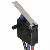
D2HW-BL221M
Description
SWITCH LEVER SPDT 2A SEALED
Manufacturer
Omron
Series
D2HWr
Type
Snap Actionr
Specifications of D2HW-BL221M
Circuit
SPDT
Switch Function
On-Mom
Contact Rating @ Voltage
2A @ 12VDC
Actuator Type
Lever, Straight
Mounting Type
Chassis Mount
Termination Style
Wire Leads
Operating Force
50gf
Contact Form
SPDT
Contact Rating
1 Amp at 24 Volts
Actuator
Lever, Hinge
Post Position
Downwards
Microswitch Type
Ultra Subminiature
Actuator Style
Hinge Lever
Switch Operation
ON-OFF
Operating Force Max
50gf
Contact Voltage Ac Nom
125V
Contact Voltage Dc Nom
42V
Body Style
Subminiature
Brand/series
D2HW Series
Current, Rating
1 A
Dielectric Strength
1500 VAC
Ip Rating
IP67
Mounting Hole Size
2.4 mm
Number Of Poles
1
Number Of Positions
2
Operation
On-Off
Standards
RoHS Compliant
Temperature, Operating
- 40 to + 85 °C
Termination
Lead Wire
Voltage, Rating
24 VDC
Lead Free Status / RoHS Status
Lead free / RoHS Compliant
Lead Free Status / RoHS Status
Lead free / RoHS Compliant, Lead free / RoHS Compliant
Other names
D2HWBL221M
SW736
SW736


D2HW
■
Note:
■
Consult your OMRON sales representative for specific models
with standard approvals.
UL1054 (File No. E41515)/CSA C22.2 No. 55 (UL
approval)
■
Note
4
SPDT
Operating speed
Operating frequency
Insulation resistance
Contact resistance
(initial value)
Dielectric strength
Vibration resistance (see note 2)
Shock resistance (see note 2)
Durability (see note 3)
Degree of protection
Degree of protection against electric
shock
Proof tracking index (PTI)
Ambient operating temperature
Ambient operating humidity
Weight
125 VAC
12 VDC
COM
(Black)
Characteristics
Approved Standards
Contact Form
1. The data given above are initial values.
2. For the pin plunger models, the above values apply for use at the free position, operating position, and total travel position. For
3. For testing conditions, consult your OMRON sales representative.
Molded lead wire colors are indicated in parentheses.
Rated voltage
the lever models, they apply at the total travel position.
The values shown apply for malfunctions of 1 ms max.
NO
(Blue)
Item
NC
(Red)
0.1 A
2 A
SPST-NC
(Molded Lead Wire Models Only)
1 mm to 500 mm/s (for pin plunger models)
30 operations/min max.
100 MΩ min. (at 500 VDC)
100 mΩ max. (molded lead wire models: 150 mΩ max.)
600 VAC, 50/60 Hz for 1 min between terminals of the same polarity
1,500 VAC, 50/60 Hz for 1 min between current-carrying metal parts and ground, and between
each terminal and non-current-carrying metal parts
Malfunction: 10 to 55 Hz, 1.5-mm double amplitude
Destruction: 1,000 m/s
Malfunction: 300 m/s
Mechanical: 1,000,000 operations min. (30 operations/min)
Electrical: 100,000 operations min. (20 operations/min)
IEC IP67 (excluding the terminals on terminal models)
Class I
175
–40 to 85°C (at ambient humidity of 60% max.) (with no icing or condensation)
95% max. (for 5 to 35°C)
Approx. 0.7 g (for pin plunger models with terminals)
D2HW
COM
(Black)
NC
(Red)
2
2
{approx. 30 G} max.
{approx. 100 G} max.
■
Note:
Contact
Minimum applicable load
(see note)
Contact Specifications
Minimum applicable loads are indicated by N standard ref-
erence values. This value represents the failure rate at a
60% (λ60) reliability level.
The equation λ60=035×10−6/operations indicates that a
failure rate of 1/2,000,000 operations can be expected at
a reliability level of 60%.
Specification
Specification
Material
Gap (standard value) 0.5 mm
SPST-NO
(Molded Lead Wire Models Only)
Item
COM
(Black)
NO
(Blue)
Crossbar
Gold alloy
1 mA at 5 VDC
Specification
D2HW
Related parts for D2HW-BL221M
Image
Part Number
Description
Manufacturer
Datasheet
Request
R

Part Number:
Description:
SUBMINIATURE BASIC SWITCH
Manufacturer:
Omron
Datasheet:
Part Number:
Description:
SUBMINIATURE BASIC SWITCH
Manufacturer:
Omron
Datasheet:
Part Number:
Description:
SUBMINIATURE BASIC SWITCH
Manufacturer:
Omron
Datasheet:
Part Number:
Description:
SUBMINIATURE BASIC SWITCH
Manufacturer:
Omron
Datasheet:
Part Number:
Description:
SUBMINIATURE BASIC SWITCH
Manufacturer:
Omron
Datasheet:
Part Number:
Description:
SUBMINIATURE BASIC SWITCH
Manufacturer:
Omron
Datasheet:
Part Number:
Description:
SUBMINIATURE BASIC SWITCH
Manufacturer:
Omron
Datasheet:
Part Number:
Description:
SWITCH SUBMINIATURE BASIC SPDT
Manufacturer:
Omron
Datasheet:
Part Number:
Description:
SWITCH SUBMINIATURE BASIC SPDT
Manufacturer:
Omron
Datasheet:
Part Number:
Description:
SWITCH SUBMINI BASIC SPDT-NO
Manufacturer:
Omron
Datasheet:
Part Number:
Description:
SWITCH SUBMINIATURE BASIC SPDT
Manufacturer:
Omron
Datasheet:
Part Number:
Description:
SWITCH SUBMINI BASIC SPST-NO
Manufacturer:
Omron
Datasheet:

Part Number:
Description:
SWITCH SUBMINI BASIC SPDT-NO
Manufacturer:
Omron
Datasheet:

Part Number:
Description:
SWITCH BASIC SPDT 2A SEALED
Manufacturer:
Omron
Datasheet:

Part Number:
Description:
SWITCH LEVER SPDT 2A SEALED
Manufacturer:
Omron
Datasheet: