D2SW-P01L3T Omron, D2SW-P01L3T Datasheet - Page 5
D2SW-P01L3T
Manufacturer Part Number
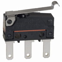
D2SW-P01L3T
Description
SWITCH SIM ROLL SPDT .1A .110QC
Manufacturer
Omron
Series
D2SW-Pr
Type
Basic/Snap Actionr
Specifications of D2SW-P01L3T
Circuit
SPDT
Switch Function
On-Mom
Contact Rating @ Voltage
0.1A @ 30VDC
Actuator Type
Lever, Simulated Roller
Mounting Type
Chassis Mount
Termination Style
Quick Connect - .110" (2.8mm)
Operating Force
61gf
Contact Form
SPDT
Contact Rating
0.1 Amp at 30 Volts
Actuator
Simulated Roller Lever
Ingress Protection
IP67, Watertight
Microswitch Type
Subminiature
Actuator Style
Simulated Roller Lever
Operating Force Max
0.6N
Contact Voltage Ac Nom
125V
Contact Voltage Dc Nom
30V
Contact Current Max
100mA
Body Style
Subminiature
Current, Rating
0.1 A
Dielectric Strength
1500 VAC
Force, Operating
1.8 N (Max.)
Ip Rating
IP67
Mounting Hole Size
M2.3
Number Of Poles
1
Operation
Snap Action
Standards
UL Recognized
Temperature Rating
-20 to +70 °C
Termination
Quick Connect
Voltage, Rating
30 VDC
Lead Free Status / RoHS Status
Lead free / RoHS Compliant
Lead Free Status / RoHS Status
Lead free / RoHS Compliant, Lead free / RoHS Compliant
Other names
D2SWP01L3T
SW805
Z2123
Z2123
SW805
Z2123
Z2123


Precautions
■ Cautions
Degree of Protection
Do not use this product in water. Although these models satisfy the
test conditions for the standard given below, this test is to check the
ingress of water into the switch enclosure after submerging the
Switch in water for a given time. Satisfying this test condition does
not mean that the Switch can be used in water.
IEC 60529: 2001 Degrees of protection provided by enclosures (IP
Code)
Code: IP67 (The test to meet the standard checks for water intrusion
after immersion for 30 minutes.)
Do not operate the Switch when it is exposed to water spray, or when
water drops adhere to the Switch surface, or during sudden tempera-
ture changes, otherwise water may intrude into the interior of the
Switch due to a suction effect.
Prevent the Switch from coming into contact with oil and chemicals.
Otherwise, damage to or deterioration of Switch materials may
result.
Do not use the Switch in areas where it is exposed to silicon adhe-
sives, oil, or grease, otherwise faulty contact may result due to the
generation of silicon oxide.
The environment-resistant performance of the switch differs depend-
ing on operating loads, ambient atmospheres, and installation condi-
tions, etc. Please perform an operating test of the switch in advance
under actual usage conditions.
Hinge Roller Lever Models
D2SW-P2L2@@
D2SW-P01L2@@
Simulated Roller Lever Models
D2SW-P2L3@@
D2SW-P01L3@@
t=0.3 Stainless-steel lever
t=0.3 Stainless-steel lever
2.35
2.35
+0.075
−0.05
2.5±
+0.075
-0.05
2.15
2.5±
0.07
7.3
3.2
2.15
dia.
0.07
7.3
3.2
dia.
5.15
5.15
8.55
19.8±
15.5
9.5±
8.55
19.8±
15.8±
15.5
9.5±
0.1
0.2
14.5±
0.6
0.1
0.2
0.6
A
A
Three, 1.6 dia. holes
R1.3
6.9
2.35
2.35
Three, 1.6 dia. holes
6.9
7.7
+0.075
−0.05
+0.075
-0.05
3.3±
7.7
OP
3.3±
0.1
dia. 4.8 x 3.2
Polyacetal resin roller
dia.
dia.
OP
FP
0.1
Sealed Subminiature Basic Switch
FP
Connecting to Terminals
Connecting to Solder Terminals
When soldering the lead wire to the terminal, first insert the lead wire
conductor through the terminal hole and the conduct soldering.
Make sure that the temperature at the tip of the soldering iron is 350
to 400°C. Do not take more than 3 seconds to solder the switch ter-
minal, and do not impose external force on the terminal for 1 min.
after soldering. Improper soldering involving an excessively high tem-
perature or excessive soldering time may deteriorate the characteris-
tics of the Switch.
Connecting to Quick-connect Terminals
Wire the quick-connect terminals (#110) with receptacles. Insert the
terminals straight into the receptacles. Do not impose excessive
force on the terminal in the horizontal direction, otherwise the termi-
nal may be deformed or the housing may be damaged.
Connecting to PCB Terminal Boards
When using automatic soldering baths, we recommend soldering at
260±5°C within 5 seconds. Make sure that the liquid surface of the
solder does not flow over the edge of the board.
When soldering by hand, as a guideline, solder with a soldering iron
with a tip temperature of 350 to 400°C within 3 seconds, and do not
apply any external force for at least 1 minute after soldering. When
applying solder, keep the solder away from the case of the Switch
and do not allow solder or flux to enter the case.
Side-actuated (Cam/Dog) Operation
When using a cam or dog to operate the Switch, factors such as the
operating speed, operating frequency, push-button indentation, and
material and shape of the cam or dog will affect the durability of the
Switch. Confirm performance specifications under actual operation
conditions before using the Switch in applications.
6.4±
0.5
6.4±
0.5
0.2
0.2
Model
OF max.
RF min.
OT min.
MD max.
FP max.
OP
Model
OF max.
RF min.
OT min.
MD max.
FP max.
OP
D2SW-P2L3@@
0.6 N {61 gf}
0.05 N {5 gf}
0.8 mm
0.8 mm
15.5 mm
10.7±0.8 mm
D2SW-P2L2@@
0.6 N {61 gf}
0.05 N {5 gf}
0.8 mm
0.8 mm
19.3 mm
14.5±0.8 mm
D2SW-P
D2SW-P01L3@@
D2SW-P01L2@@
5
Related parts for D2SW-P01L3T
Image
Part Number
Description
Manufacturer
Datasheet
Request
R

Part Number:
Description:
Sealed Subminiature Basic Switch
Manufacturer:
Omron Corporation
Datasheet:

Part Number:
Description:
SWITCH BASIC SPDT 2A .110QC
Manufacturer:
Omron
Datasheet:

Part Number:
Description:
SWITCH SIM ROLLER SPDT 2A SLDR
Manufacturer:
Omron
Datasheet:

Part Number:
Description:
SWITCH SIM ROLLER SPDT .1A PCB
Manufacturer:
Omron
Datasheet:

Part Number:
Description:
SWITCH BASIC SPDT .1A PCB
Manufacturer:
Omron
Datasheet:

Part Number:
Description:
SWITCH ROLLER LEVER SPDT 2A SLDR
Manufacturer:
Omron
Datasheet:
Part Number:
Description:
SWITCH SIM ROLLER SPDT .1A PCB
Manufacturer:
Omron
Datasheet:
Part Number:
Description:
SWITCH BASIC SPDT .1A .110QC
Manufacturer:
Omron
Datasheet:

Part Number:
Description:
SWITCH SIM ROLLER SPDT 2A WIRE
Manufacturer:
Omron
Datasheet:
Part Number:
Description:
SWITCH SIM ROLLER SPDT .1A WIRE
Manufacturer:
Omron
Datasheet:

Part Number:
Description:
Miniature Basic Switch
Manufacturer:
Omron
Datasheet:
Part Number:
Description:
SUBMINIATURE BASIC SWITCH
Manufacturer:
Omron
Datasheet:
Part Number:
Description:
Subminiature Basic Switch
Manufacturer:
Omron
Datasheet:
Part Number:
Description:
Subminiature Basic Switch
Manufacturer:
Omron
Datasheet:
Part Number:
Description:
Miniature Basic Switch
Manufacturer:
Omron
Datasheet: