V-15G2-1C26-K Omron, V-15G2-1C26-K Datasheet - Page 19
V-15G2-1C26-K
Manufacturer Part Number
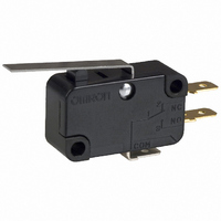
V-15G2-1C26-K
Description
SWITCH LEVER SPDT 15A .187QC
Manufacturer
Omron
Series
Vr
Type
Snap Actionr
Specifications of V-15G2-1C26-K
Circuit
SPDT
Switch Function
On-Mom
Contact Rating @ Voltage
15A @ 250VAC
Actuator Type
Lever, Straight
Mounting Type
Chassis Mount
Termination Style
Quick Connect - .187" (4.7mm)
Operating Force
250gf
Contact Form
SPDT
Contact Rating
15 Amps at 250 Volts
Actuator
Lever, Hinge
Microswitch Type
Snap Action
Actuator Style
Hinge Lever
Operating Force Max
400gf
Contact Voltage Ac Nom
250V
Contact Voltage Dc Nom
250V
Contact Current Max
15A
Lead Free Status / RoHS Status
Lead free / RoHS Compliant
Lead Free Status / RoHS Status
Lead free / RoHS Compliant, Lead free / RoHS Compliant
Other names
SW132
V15G21C26K
V15G21C26K


General Information
Operating Stroke Setting
The setting of stroke is very important for a switch to operate with
high reliability.
The chart below shows the relationship among operating force,
stroke, and contact force. To obtain high reliability from a switch, a
switch actuator must be manipulated within an appropriate range of
operating force.
Be sure to pay the utmost attention when mounting a switch.
Make sure that the operating body is set so that the actuator should
return to the free position when the operating body has moved if a
switch is used to form a normally closed (NC) circuit. If a switch is
used to form a normally open (NO) circuit, the operating body must
move the switch actuator to the distance of 70% to 100% of the rated
overtravel (OT) of the switch.
If stroke is set in the vicinity of the operating position (OP) or the re-
leasing position (RP), contact force may become unstable. As a re-
sult, the switch cannot ensure high reliability. Furthermore, the
switch may malfunction due to vibration or shock.
If stroke is set exceeding the total travel position (TTP), the moment
of inertia of the operating body may damage the actuator or the
switch itself, and the stress applied to the moving spring inside the
switch will increase and then, the durability of the switch may be de-
teriorated.
28
Mechanical Conditions
Operating
body
Incorrect
Release
Release
TTP
FP
Install a stopper.
Correct
PT (Pretravel)
Stroke
Stroke
OP (Operating position)
OT (Overtravel)
TTP
FP (Free position)
(Total travel position)
Switching Speed and Frequency
The switching frequency and speed of a switch have a great influ-
ence on the performance of the switch. Pay attention to the follow-
ing.
•
•
•
•
The permissible switching speed and switching frequency of a
switch indicate the operational reliability of the switch. The durability
of a switch is based on operation under specific conditions regard-
ing the switching speed and switching frequency. The durability of a
switch may not meet the durability due to conditions even if the
switch is operated within the permissible switching speed and fre-
quency ranges. Test a switch sample under the actual conditions to
ascertain its durability.
Operating Condition
Do not leave a switch with the actuator depressed for a long time,
otherwise the parts of the switch may soon deteriorate and the
changes of its characteristics operating may result.
Operating Method
The operating method has a great influence on the performance of a
switch. Consider the following before operating a switch.
•
If the actuator is operated too slowly, the switching operation
may become unstable, causing contact failures or contact
welding.
If the actuator is operated too quickly, the switch may be
damaged by shock.
If the switching frequency is too high, the switching of the
contacts cannot catch up with the operating speed of the
actuator.
If the operating frequency is extremely low (i.e., once a month or
less frequent), a film may be generated on the surface of the
contacts, which may cause contact failures.
Design the operating body (i.e., cam or dog) so that it will operate
the actuator smoothly. If the actuator snaps backwards quickly or
receives shock due to the shape of the operating body, its
durability may be deteriorated.
Incorrect
Correct
Shock operation
Snap-back
General Information
Related parts for V-15G2-1C26-K
Image
Part Number
Description
Manufacturer
Datasheet
Request
R

Part Number:
Description:
SWITCH LEVER SPDT 15A .187QC
Manufacturer:
Omron
Datasheet:

Part Number:
Description:
SWITCH LEVER SPDT 15A .187QC
Manufacturer:
Omron
Datasheet:

Part Number:
Description:
MINIATURE BASIC SWITCH
Manufacturer:
Omron
Datasheet:
Part Number:
Description:
MINIATURE BASIC SWITCH
Manufacturer:
Omron
Datasheet:
Part Number:
Description:
MINIATURE BASIC SWITCH
Manufacturer:
Omron
Datasheet:
Part Number:
Description:
MINIATURE BASIC SWITCH
Manufacturer:
Omron
Datasheet:
Part Number:
Description:
Miniature Basic Switch
Manufacturer:
Omron
Datasheet:
Part Number:
Description:
RELAYS
Manufacturer:
Omron
Datasheet:

Part Number:
Description:
MICRO SWITCH, PIN PLUNGER, SPDT 15A 250V
Manufacturer:
Omron
Datasheet:

Part Number:
Description:
SWITCH BASIC SPDT 15A 200GF
Manufacturer:
Omron
Datasheet:

Part Number:
Description:
SWITCH BASIC SPST 15A .187QC
Manufacturer:
Omron
Datasheet:
Part Number:
Description:
SWITCH BASIC SPDT 15A 400GF
Manufacturer:
Omron
Datasheet:
Part Number:
Description:
SWTCH MINI SPST-NC 15A PIN PLNGR
Manufacturer:
Omron
Datasheet:
Part Number:
Description:
MINIATURE BASIC SWITCH
Manufacturer:
Omron
Datasheet: