WGLA1A01AA1A Honeywell Sensing and Control, WGLA1A01AA1A Datasheet
WGLA1A01AA1A
Specifications of WGLA1A01AA1A


Related parts for WGLA1A01AA1A

WGLA1A01AA1A Summary of contents
Page 1
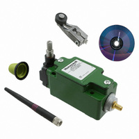
Installation and Technical Manual for the Limitless™ Series WGLA Limit Switch used in conjunction with the Limitless™ WPMM Series WARNING PERSONAL INJURY • DO NOT USE these products as safety or emergency stop devices or in any other application where ...
Page 2
... Outdoor Installation Warnings ......................................................................................................................... 22 6.2.3 Antenna Connection, Styles, and Mounting Options ................................................................................... 23 6.2.3.1 Antenna Connection, Styles, and Mounting Options ................................................................................................... 23 6.2.3.2 Antenna Styles and Mounting Options .......................................................................................................................... 23 6.2.4 Antenna Adjustment Considerations .............................................................................................................. 26 6 IGNAL ANGE OF AN NTENNA ii Honeywell Sensing and Control ............................................................................................................................................. 1 ................................................................................................................................ 3 ......................................................................................................................................... 5 .................................................................................................................................. 6 .................................................................................................................................. 6 ....................................................................................................................................... 6 ................................................................................................................................ 7 ............................................................................................................................ ............................................................................................ 9 ONFORMITY O ROCEDURE .......................................................................................................................... 13 LED FUNCTIONS ...
Page 3
... ACCESSORIES ................................................................................................................................................................. 35 8.1 A CTUATORS .................................................................................................................................................................. 35 8 NTENNA PTIONS ...................................................................................................................................................... 36 8 NTENNA ABLE PTIONS 8 OUNTING PTIONS .................................................................................................................................................... 38 9 INSTALLATION DRAWINGS ......................................................................................................................................... 39 9 RAWING VAILABILITY ............................................................................................................................................... 39 10 TROUBLESHOOTING GUIDES ................................................................................................................................. AIN D I ITH CCEPTABLE ADE ............................................................................................................................. 28 A CTUATORS ............................................................................................................ 30 EPLACEMENT .................................................................................................................... 33 R EPLACEMENT ................................................................................................................ 33 .......................................................................................................................................... 37 50051863 Issue 2 ARGIN .................................................................. 27 Honeywell Sensing and Control iii ...
Page 4
... Table 7 – Approvals and Ratings ................................................................................................................................. 6 Table 8 – Radio Module Specifications ........................................................................................................................ 6 Table 9 – Electrical Specifications ................................................................................................................................ 6 Table 10 – Environmental Specifications ...................................................................................................................... 7 Table 11 – EIRP Limits Per Antenna ........................................................................................................................... 11 Table 12 – Cable/Connector Loss Per Antenna Type for the WGLA Series .............................................................. 11 vi Honeywell Sensing and Control 50051863 Issue 2 ...
Page 5
... The WGLA will transmit the position of its actuator to a Limitless™ Wireless Panel Mount Monitor (WPMM Series). The WPMM will then indicate the actuator position of the WGLA via a visual indicator, audible indicator and/or electronic output. The WGLA supports no electrical signal inputs and is powered by a replaceable battery. 50051863 Issue 2 Honeywell Sensing and Control 1 ...
Page 6
... Limitless™ WGLA Series 1.3 Model Reference 2 Honeywell Sensing and Control 50051863 Issue 2 ...
Page 7
... Maximum Permissible Exposure North America – United States of America and Canada National Electrical Manufacturers Association Radio and Telecommunications Terminal Equipment Reverse Polarity SMA connector Radio Frequency Transmit Wireless Global Limit Switch Series Wireless Panel Mount Monitor Series 50051863 Issue 2 Honeywell Sensing and Control 3 ...
Page 8
... R&TTE Directive, the CE Mark and the notified body (NB) identification number is used when the NB is involved in the conformity assessment procedure. The alert sign must be used when a restriction on use (output power limit by a country at certain frequencies) applies to the equipment and must follow the CE marking. 4 Honeywell Sensing and Control 50051863 Issue 2 Definition ...
Page 9
... Country AT Latvia BE Lithuania BG Luxembourg CY Malta CZ Netherlands DK Poland EE Portugal FI Romania FR Slovak Republic DE Slovenia GR Spain HU Sweden IE United Kingdom IT ISO 3166 2 letter code Country BA Norway HR Russian Federation IS Serbia LI Switzerland MK Turkey 50051863 Issue 2 ISO 3166 2 letter code ISO 3166 2 letter code Honeywell Sensing and Control 5 ...
Page 10
... The latest applicable EMC Standards are as follows: • EN 300 328, V1.7.1 • EN 61326-1 (2006) • EN 301 489-1, V1.8.1 • EN 301 489-17, V2.1.1 6 Honeywell Sensing and Control Specification IEEE 802.15.4 WPAN Direct Sequence Spread Spectrum (DSSS), 2.4 GHz 250 kbps ISM 2.4 GHz ...
Page 11
... French: Cet appareil numérique de la classe B est conforme à la norme NMB-003 du Canada. Specification -25 ° °C [-13 °F to 185 °F] ; Side rotary to -40 °C [40 °F] -25 ° °C [-13 °F to 185 °F] ; Side rotary to -40 °C [40 °F] 0 %RH to 100 %RH 50051863 Issue 2 Honeywell Sensing and Control 7 ...
Page 12
... European Restrictions • Information regarding national restrictions can be found in document: ERC/REC 70-03 (Relating to the use of short-range devices including appendixes and annexes). Documentation may be found in the document database in the European Communication’s office. • http://www.erodocdb.dk/doks/dochistory.aspx?docintid=1622 8 Honeywell Sensing and Control 50051863 Issue 2 ...
Page 13
... Limitless™ WGLA Series 2.8 European (CE) Declaration of Conformity (DoC) 2.8.1 European Declaration of Conformity Statements This section contains the European Declaration of Conformity (DoC) statement for the radio used in the Limitless™ WGLA switch. Figure 1. European Declaration of Conformity (DoC) 50051863 Issue 2 Honeywell Sensing and Control 9 ...
Page 14
... Omni remote antenna used in ETSI/European Countries including France restriction EIRP = 8 dBm – 4. 5.5 dBi EIRP = 8.97 dBm (value is less than the max. EIRP allowed of 10.00 dBm) Antenna gain is expressed relative to a (theoretical) isotropic reference antenna (dBi). 10 Honeywell Sensing and Control 50051863 Issue 2 ...
Page 15
... FCC, IC/USA, Canada Remote* ACMA/Australia Integral** or FCC, IC/USA, Canada Remote** Integral** or ACMA/Australia Remote** ETSI/European Countries including France 50051863 Issue 2 Max. radio output power Max. EIRP (dBm) (dBm) 36. 19.24 8 10.00*** 18 36.00 19. 10.00*** 18 36.00 19. 10.00*** 18 36.00 8 19.24 18 36.00 8 19.24 Honeywell Sensing and Control 11 ...
Page 16
... WGLA connector jack under the same mounting procedure as the direct mount antenna. The other end of the extension cable will need to mate with antenna connector directly. Refer to Section 6.3 for further information regarding installation. 12 Honeywell Sensing and Control 50051863 Issue 2 ® ...
Page 17
... Replace cover and retighten screws or immediately proceed to Section 5.3 Pairing Mode. Figure 2. Limitless™ Switch Housing on the housing cover. and remove the battery insulator Figure 3. Limitless™ Battery and Insulator 50051863 Issue 2 . Insure that the Honeywell Sensing and Control 13 ...
Page 18
... ATTENTION The purging of a WGLA per Section 5.4 is required when a previously paired WGLA is desired to be paired again. 14 Honeywell Sensing and Control on the housing cover (See Figure 4) of the WGLA and locate on WPMM (See Figure 5) for more than four seconds and less than ...
Page 19
... Figure 6. Limitless™ Switch with Function Button Depressed NOTE: Use a blunt object, such as a paper clip or tooth pick to actuate the function switch . Figure 7. Limitless™ Switch Label Placement 50051863 Issue 2 . Honeywell Sensing and Control 15 ...
Page 20
... The operation and LED functions for the WPMM are visually depicted and described in the attached file. This file is also located as a separate file on this www.honeywell.com/sensing. 16 Honeywell Sensing and Control on the housing cover of the WGLA (See Figure 4) and locate the ...
Page 21
... Limitless™ WGLA Series Figure 8. WPMM Operation and LED Functions Chart – part 1 50051863 Issue 2 Honeywell Sensing and Control 17 ...
Page 22
... Limitless™ WGLA Series Figure 9. WPMM Operation and LED Functions Chart – part 2 18 Honeywell Sensing and Control 50051863 Issue 2 ...
Page 23
... UV stable 316 coax, UV stable SST fiberglass Polyethylene/200 aluminum Series coax alloy UV stable PVC/RG- 300 series UV stable 316 coax, UV stable SST fiberglass Polyethylene/200 aluminum Series coax alloy UV stable LG UV stable PVC/ UV stable Keyflex BT- RG-174 coax black ABS 1040D Honeywell Sensing and Control 19 ...
Page 24
... For instance, this is analogous to the reflector in an automobile’s headlight. The reflector does not add light or increase the luminous intensity of the light bulb, rather it simply directs all the light energy in the forward direction where the light is needed most. 20 Honeywell Sensing and Control 2.2 dBi RF Antenna Pattern - Horizontal 50051863 Issue 2 2 ...
Page 25
... Generally, the higher the antenna is above ground, the better it performs. Another concern is RF interference, discussed in Section 1.5.3. Figure 11. WGLA to WPMM Antennas with RF Signal Line of Sight (LOS) Free From Obstacles Figure 12. WGLA to WPMM Antennas with RF Signal Line of Sight (LOS) Affected by Obstacles 50051863 Issue 2 Honeywell Sensing and Control 21 ...
Page 26
... Use a non-conductive dry board, stick, or rope to push, pull, or drag them so they no longer are in contact with electrical power. • Once they are no longer contacting electrical power, administer CPR if certified, and make sure emergency medical aid has been requested. 22 Honeywell Sensing and Control 50051863 Issue 2 ...
Page 27
... It is also more resistant to weather conditions as there’s no swivel-joint connection for contaminants to enter. A benefit of the tilt & swivel design is that it allows easier positioning in relation to other antenna(s) to obtain a suitable RF signal. Issue 2 Figure 14. Limitless™ WGLA RP-SMA Connection, Remote Honeywell Sensing and Control 23 50051863 ...
Page 28
... Permanent mounting: Pre-clean the surface where the antenna mounted with an alcohol wipe. Peel paper protection from adhesive strip and mount to the cleaned surface. Figure 16. Adhesive Mount Antenna – Step 1. Pre-clean the surface 24 Honeywell Sensing and Control Figure 17. Adhesive Mount Antenna – Step 2. Peel Protection from Adhesive Strip 50051863 Issue 2 Figure 18. Adhesive Mount Antenna – ...
Page 29
... Assemble two U-clamps around mast and tighten nuts to ensure lock washers provided are compressed to a flat condition. Figure 19. Mast Mount Antenna – Tighten nut on mounting bracket Issue 2 Figure 20. Mast Mount Antenna – Side View with Attachment to Pipe Honeywell Sensing and Control 25 50051863 ...
Page 30
... Line of sight with a 2.2 dBi antenna installed on the WGLA switch and WPMM monitor 26 Honeywell Sensing and Control 50051863 Issue 2 Figure 21. Magnetic Mount Bracket with Antenna – Mounted on Steel ...
Page 31
... Crystek – Part number: CATTEN-0100) • RP-SMA female to SMA male connector adaptor (i.e. Connector City – Part number : ADP-SMAM-RPSF) • RP-SMA male to SMA female connector adaptor (i.e. Connector City – Part number : ADP-RPSM-SMAF) 50051863 Issue 2 Honeywell Sensing and Control 27 ...
Page 32
... A lightning arrestor such as the AL-NFNFB-9 from Hyperlink Technologies can be reviewed against application requirements. ATTENTION National, local and/or regulatory agencies may require the use of a lightning arrestor and possibly other requirements for an antenna system installation recommended that the customer review and adhere to these requirements. 28 Honeywell Sensing and Control 50051863 Issue 2 ...
Page 33
... Once the RF sources are identified and located, it may allow the Limitless™ Series antennas to be moved away from the identified RF sources to achieve acceptable performance. The other option is removing the external source, if feasible. 50051863 Issue 2 Honeywell Sensing and Control 29 ...
Page 34
... Figure 23. Limitless™ WGLA mounting hole diagram The WGLA Series switch has many actuator types and associated specifications (see below). Additional information regarding the instructions for reading of the bar charts can be found at: www.honeywell.com/sensing 30 Honeywell Sensing and Control 50051863 Issue 2 ...
Page 35
... Limitless™ WGLA Series Figure 24. Limitless™ Switch Actuator characteristics Side Rotary Head with GLZ51 Series Lever Issue 2 Side Rotary Head with GLZ52 Series Lever Honeywell Sensing and Control 31 50051863 ...
Page 36
... Limitless™ WGLA Series Side Rotary Head with GLZ54 Series Lever 32 Honeywell Sensing and Control Issue 2 Top Pin Plunger Head 50051863 ...
Page 37
... Failure to comply with these instructions could result in death or serious injury. ATTENTION Use only the following 3.6V lithium thionyl chloride (Li-SOCl2) battery (non-rechargeable), size 2/3AA. No other batteries are approved for use in the WGLA Series limit switch. • Uniwell, DEV-10-0009 • Honeywell, WBT1 50051863 Issue 2 Honeywell Sensing and Control 33 ...
Page 38
... Do not disassemble and do not expose of in fire. Note: Re-pairing via pairing mode is not required after installing a new battery Figure 25. Limitless™ WGLA Battery Replacement 34 Honeywell Sensing and Control on the housing cover. needed, pry out battery by using a slotted screwdriver as a ...
Page 39
... Limitless™ WGLA Series 8 ACCESSORIES 8.1 Actuators 50051863 Issue 2 Honeywell Sensing and Control 35 ...
Page 40
... Limitless™ Antennas WAN01RSP WAN02RSP Straight Tilt and Swivel Design Direct Design, Direct Mount Mount Antenna Connector 36 Honeywell Sensing and Control WAN05RSP with WAN03RSP Flat Design, WAMM100RSP-005 Adhesive Mount Antenna Tilt and Swivel Design, Magnetic Mount Antenna 50051863 Issue 2 WAN06RNJ Straight Design, Bracket ...
Page 41
... Limitless™ WGLA Series 8.3 Antenna Cable Options Limitless™ Cable Accessories WCA200RNPRSP-002/010 Cable Assembly 50051863 Issue 2 Honeywell Sensing and Control 37 ...
Page 42
... Limitless™ WGLA Series 8.4 Mounting Options Limitless™ Panel Mount Accessories WAMM100RSP-005/010 Magnetic Antenna Mount 38 Honeywell Sensing and Control 50051863 Issue 2 ...
Page 43
... Limitless™ WGLA Series 9 INSTALLATION DRAWINGS 9.1 Drawing Availability Complete installation drawings for each listing of the Limitless™ WGLA Series switch and accessories are available at www.honeywell.com/sensing 50051863 Issue 2 Honeywell Sensing and Control 39 ...
Page 44
... LED on and possibly incorrect amber and red LED indication/output for seconds. Amber LED is flashing Amber LED is constantly ON 40 Honeywell Sensing and Control CAUSE RESOLUTION 10 Vdc to 30 Vdc is not Check for proper connection and 10 Vdc to 30 applied to "+" & "-" terminals Vdc to " ...
Page 45
... External actuator of Replace Limitless™ actuator Limitless™ switch damaged Actuating head of Limitless™ Replace Limitless™ actuating head switch damaged Limitless™ switch internal Replace Limitless™ switch electronics damaged Damaged output Replace WPMM 50051863 Issue 2 Honeywell Sensing and Control 41 ...
Page 46
Limitless™ WGLA Series WARRANTY/REMEDY Honeywell warrants goods of its manufacture as being free of defective materials and faulty workmanship. Honeywell’s standard product warranty applies unless agreed to otherwise by Honeywell in writing; please refer to your order acknowledgement or consult ...