B3U-1000P Omron, B3U-1000P Datasheet

SWITCH TACT SPST W/O GND SMD

B3U-1000P

Manufacturer Part Number
B3U-1000P
Description
SWITCH TACT SPST W/O GND SMD
Manufacturer
Omron
Series
B3Ur
Datasheets

Specifications of B3U-1000P

Operating Force
153gf
Circuit
SPST-NO
Switch Function
Off-Mom
Contact Rating @ Voltage
0.05A @ 12VDC
Actuator Type
Standard
Mounting Type
Surface Mount
Orientation
Vertical
Outline
3.00mm x 2.50mm
Illumination
Non-Illuminated
Actuator
Top
Contact Current Rating
1 mAmp to 50 mAmps at 5 Volts to 12 Volts
Ground Terminal
No
Contact Form
SPST - NO
Termination Style
Solder Pad
Body Size
2.5 mm L x 3 mm W x 1.2 mm H
Features
Ultra-Small Tactile Switch with High Contact Reliability
Operating Temperature Range
- 25 C to + 70 C
Contact Configuration
SPST-NO
Contact Voltage Dc Nom
12V
Contact Current Max
50mA
Actuation Type
Top
Switch Terminals
Surface Mount
Svhc
No SVHC (15-Dec-2010)
Contact
RoHS Compliant
Contact Rating
1 mAmp to 50 mAmps at 5 Volts to 12 Volts
Circuitry
SPST-NO
Operating Force Max
153gf
Rohs Compliant
Yes
Actuator / Cap Color
Black
Lead Free Status / RoHS Status
Lead free / RoHS Compliant
Lead Free Status / RoHS Status
Lead free / RoHS Compliant
Other names
B3U1000P
SW1020TR

Available stocks

Company
Part Number
Manufacturer
Quantity
Price
Part Number:
B3U-1000P
Manufacturer:
OMRON
Quantity:
8 000
Part Number:
B3U-1000P-B
Quantity:
3 030
Ultra-small-sized Tactile Switch with
High Contact Reliability:
Ordering Information
Note:
Operating Characteristics
Dimensions
Note:
Operation
type
Top-
actuated
Side-
actuated
Item
Operating force (OF)
Releasing force (RF)
Pretravel (PT)
Without Ground Terminal, without Boss
2.5
B3U-1000P
Industry’s smallest switch* allows high-density
mounting on PCBs for mobile equipment.
Dust-proof construction provides high reliability in
dusty environments.
Surface mounted: Ideal for high-density mounting.
Models with ground terminals are available for
protection against static electricity.
Top-actuated Models
1.2 × 3 × 2.5 mm (H × W × D)
RoHS Compliant
Ultra-small Tactile Switch
*As of October 2006 (according to OMRON survey).
1.4
Operation type
Orders must be made in multiples of the order unit speci-
fied above.
All dimensions are in millimeters unless otherwise indicated. Unless otherwise specified, a tolerance of ±0.2 mm applies to all di-
mensions.
Order
unit
3,500
pieces
4,000
pieces
4
3
1.5 dia.
Without
boss
With boss
Without
boss
With boss
Packaging
terminal
Ground
1.50 ± 0.49 N
0.2 N min.
0.15
(B3U-1000 Series)
Top-actuated
+0.2
−0.1
1.6
mm
Without ground
B3U-1000P
B3U-1000P-B
B3U-3000P
B3U-3000P-B
+0.15
−0.10
terminal
1.2
Embossed taping
+0.15
−0.10
1.7±
1.59 ± 0.49 N
0.2
(B3U-3000 Series)
PCB Mounting
0.1
Side-actuated
+0.2
−0.1
(Top View)
B3U-1100P
B3U-1100P-B
B3U-3100P
B3U-3100P-B
With ground
mm
terminal
4.2±
2.6±
0.1
0.1
2.5
With Ground Terminal, without Boss
B3U-1100P
Specifications
Item
Switching
capacity
Ambient operating
temperature
Ambient humidity
Contact
configuration
Contact
resistance
Insulation
resistance
Dielectric strength 250 VAC, 50/60 Hz for 1 min
Bounce time
Vibration
resistance
Shock resistance
Life expectancy
Maximum
operating force
Weight
1.4
Ratings/Characteristics
1.5 dia.
Operation
4
3
type
0.5
1 to 50 mA, 5 to 12 VDC (resistive load)
− 25 to 70 ° C, 60% humidity (with no icing or conden-
sation)
35% to 85% (at 5 to 35 ° C)
SPST-NO
100 m Ω max. (initial value) (rated: 1 mA, 5 VDC)
100 M Ω min. (at 100 VDC)
5 ms max.
10 to 55 Hz, 1.5 mm double amplitude
1,000 m/s
200,000 operations min. 100,000 operations min.
30 N max.
Approx. 0.022 g
1.9
(B3U-1000 Series)
Top-actuated
1.6
2
+0.15
−0.10
max.
1.2
+0.15
−0.10
1.7±
0.1
B3U
PCB Mounting
(B3U-3000 Series)
(Top View)
Side-actuated
4.2±
2.6±
0.8 ±
0.1
0.1
0.1
1.1 ±
1.1 ±
1
0.1
0.1

Related parts for B3U-1000P

B3U-1000P Summary of contents

Page 1

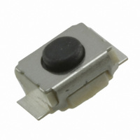
... Pretravel (PT) 0.15 mm −0.1 Dimensions Note: All dimensions are in millimeters unless otherwise indicated. Unless otherwise specified, a tolerance of ±0.2 mm applies to all di- mensions. Top-actuated Models ■ Without Ground Terminal, without Boss B3U-1000P +0.15 1.6 −0.10 4 1.2 3 2.5 1.4 1.5 dia. Specifications Ratings/Characteristics Embossed taping ■ ...

Page 2

... B3U Without Ground Terminal, with Boss B3U-1000P-B +0.15 1.6 −0. 1.2 2.5 1.4 1.5 dia. 0.5 0.65 ± 0.05 dia. Side-actuated Models ■ Note: Unless otherwise specified, a tolerance of ±0.2 mm applies to all dimensions. Without Ground Terminal, without Boss B3U-3000P 4 3 +0.15 1.2 − ...

Page 3

... Preheating time 60 to 120 Washing B3U Switches cannot be washed. Doing so will cause the wash- ing agent, together with flux or dust particles on the PCB, to enter the Switch, resulting in malfunction. Compliance with RoHS Directive The “RoHS Compliant” designation indicates that the product does not contain the following six hazardous substances covered by the RoHS Directive ...

Page 4

... To convert millimeters into inches, multiply by 0.03937. To convert grams into ounces, multiply by 0.03527. Cat. No. A162-E1-03 In the interest of product improvement, specifications are subject to change without notice. OMRON Corporation Electronic Components Company Switch Division Manual Switch Department Shiokoji Horikawa, Shimogyo-ku, Kyoto, 600-8530 Japan Tel: (81)75-344-7096/Fax: (81)75-344-7188 B3U Printed in Japan 1106-3M (1006) (C) ...

Page 5

... Confirm the conditions beforehand. Do not use an automatic soldering bath for surface-mounted Resin sheet Switches. The soldering gas or flux may enter the Switch and damage the Switch’s push-button operation. 4. Manual Soldering (All Models) Soldering temperature: 350 ° C max. at the tip of the soldering iron Soldering time max ...

Page 6

... Switch through respira- tion as the Switch cools. Wait for at least three minutes after sol- dering before cleaning washable models. Do not use Sealed Switches while submersed in water or in loca- tions exposed to water. Switch Packaging (Taping Specification Models) 1 ...

Page 7

... Make sure that the polarity of the LEDs is correct. The polarity is not indicated on the Switch, but the positive pole is located on the back surface of the Switch on the side without the OMRON mark. Connect limiting resistors to the LEDs. The Switch does not have built-in limiting resistors, so satisfy the LED characteristics by obtaining the limiting resistance according to the following formula based on the voltage to be used ...

Related keywords