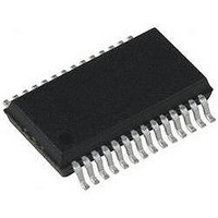
PIC18LF24K22-I/SS Microchip Technology, PIC18LF24K22-I/SS Datasheet - Page 486

PIC18LF24K22-I/SS
Manufacturer Part Number
PIC18LF24K22-I/SS
Description
IC PIC MCU 16KB FLASH 28SSOP
Manufacturer
Microchip Technology
Series
PIC® XLP™ 18Fr
Specifications of PIC18LF24K22-I/SS
Core Size
8-Bit
Program Memory Size
16KB (8K x 16)
Core Processor
PIC
Speed
64MHz
Connectivity
I²C, SPI, UART/USART
Peripherals
Brown-out Detect/Reset, HLVD, POR, PWM, WDT
Number Of I /o
24
Program Memory Type
FLASH
Eeprom Size
256 x 8
Ram Size
768 x 8
Voltage - Supply (vcc/vdd)
1.8 V ~ 3.6 V
Data Converters
A/D 19x10b
Oscillator Type
Internal
Operating Temperature
-40°C ~ 85°C
Package / Case
28-SSOP (0.200", 5.30mm Width)
Controller Family/series
PIC18
No. Of I/o's
25
Eeprom Memory Size
256Byte
Ram Memory Size
768Byte
Cpu Speed
64MHz
No. Of Timers
7
Lead Free Status / RoHS Status
Lead free / RoHS Compliant
- Current page: 486 of 496
- Download datasheet (5Mb)
PIC18(L)F2X/4XK22
Extended Instruction Set
F
Fail-Safe Clock Monitor .............................................. 44, 349
Fast Register Stack ............................................................ 72
Fixed Voltage Reference (FVR)
Flash Program Memory ...................................................... 95
G
GOTO ............................................................................... 388
H
Hardware Multiplier .......................................................... 111
High/Low-Voltage Detect ................................................. 343
DS41412D-page 486
Synchronous Slave Mode
ADDFSR .................................................................. 410
ADDULNK ................................................................ 410
and Using MPLAB Tools .......................................... 416
CALLW ..................................................................... 411
Considerations for Use ............................................ 414
MOVSF .................................................................... 411
MOVSS .................................................................... 412
PUSHL ..................................................................... 412
SUBFSR .................................................................. 413
SUBULNK ................................................................ 413
Syntax ...................................................................... 409
Fail-Safe Condition Clearing ...................................... 44
Fail-Safe Detection .................................................... 44
Fail-Safe Operation .................................................... 44
Reset or Wake-up from Sleep .................................... 44
Associated Registers ............................................... 338
Associated Registers ............................................... 103
Control Registers ....................................................... 96
Erase Sequence ...................................................... 100
Erasing ..................................................................... 100
Operation During Code-Protect ............................... 103
Reading ...................................................................... 99
Table Pointer
Table Pointer Boundaries .......................................... 98
Table Reads and Table Writes .................................. 95
Write Sequence ....................................................... 101
Writing To ................................................................. 101
Introduction .............................................................. 111
Operation ................................................................. 111
Performance Comparison ........................................ 111
Applications .............................................................. 346
Associated Registers ............................................... 347
Characteristics ......................................................... 440
Current Consumption ............................................... 345
Effects of a Reset ..................................................... 347
Operation ................................................................. 344
Setup ........................................................................ 345
Associated Registers, Transmit ............... 284, 289
Reception ......................................................... 286
Transmission .................................................... 283
Associated Registers, Receive ........................ 290
Reception ......................................................... 290
Transmission .................................................... 288
EECON1 and EECON2 ..................................... 96
TABLAT (Table Latch) Register ......................... 98
TBLPTR (Table Pointer) Register ...................... 98
Boundaries Based on Operation ........................ 98
Protection Against Spurious Writes ................. 103
Unexpected Termination .................................. 103
Write Verify ...................................................... 103
During Sleep .................................................... 347
Preliminary
HLVD. See High/Low-Voltage Detect. ............................. 343
I
I
ID Locations ............................................................. 349, 365
INCF ................................................................................ 388
INCFSZ ............................................................................ 389
In-Circuit Debugger .......................................................... 365
In-Circuit Serial Programming (ICSP) ...................... 349, 365
Indexed Literal Offset Addressing
Indexed Literal Offset Mode ............................................. 414
Indirect Addressing ............................................................ 91
INFSNZ ............................................................................ 389
Instruction Cycle ................................................................ 74
Instruction Flow/Pipelining ................................................. 74
Instruction Set .................................................................. 367
2
C Mode (MSSPx)
Start-up Time ........................................................... 345
Typical Low-Voltage Detect Application .................. 346
Acknowledge Sequence Timing .............................. 246
Bus Collision
Effects of a Reset .................................................... 247
I
Master Mode
Multi-Master Communication, Bus Collision and Arbitra-
Multi-Master Mode ................................................... 247
Read/Write Bit Information (R/W Bit) ....................... 223
Slave Mode
Sleep Operation ....................................................... 247
Stop Condition Timing ............................................. 246
and Standard PIC18 Instructions ............................. 414
Clocking Scheme ....................................................... 74
ADDLW .................................................................... 373
ADDWF .................................................................... 373
ADDWF (Indexed Literal Offset Mode) .................... 415
ADDWFC ................................................................. 374
ANDLW .................................................................... 374
ANDWF .................................................................... 375
BC ............................................................................ 375
BCF ......................................................................... 376
BN ............................................................................ 376
BNC ......................................................................... 377
BNN ......................................................................... 377
BNOV ...................................................................... 378
BNZ ......................................................................... 378
BOV ......................................................................... 381
BRA ......................................................................... 379
BSF .......................................................................... 379
BSF (Indexed Literal Offset Mode) .......................... 415
BTFSC ..................................................................... 380
BTFSS ..................................................................... 380
BTG ......................................................................... 381
BZ ............................................................................ 382
CALL ........................................................................ 382
CLRF ....................................................................... 383
CLRWDT ................................................................. 383
COMF ...................................................................... 384
CPFSEQ .................................................................. 384
CPFSGT .................................................................. 385
2
C Clock Rate w/BRG ............................................. 254
During a Repeated Start Condition .................. 251
During a Stop Condition .................................. 252
Operation ......................................................... 238
Reception ........................................................ 244
Start Condition Timing ............................. 240, 241
Transmission ................................................... 242
tion ................................................................... 248
Transmission ................................................... 228
2010 Microchip Technology Inc.
Related parts for PIC18LF24K22-I/SS
Image
Part Number
Description
Manufacturer
Datasheet
Request
R

Part Number:
Description:
Manufacturer:
Microchip Technology Inc.
Datasheet:

Part Number:
Description:
Manufacturer:
Microchip Technology Inc.
Datasheet:

Part Number:
Description:
Manufacturer:
Microchip Technology Inc.
Datasheet:

Part Number:
Description:
Manufacturer:
Microchip Technology Inc.
Datasheet:

Part Number:
Description:
Manufacturer:
Microchip Technology Inc.
Datasheet:

Part Number:
Description:
Manufacturer:
Microchip Technology Inc.
Datasheet:

Part Number:
Description:
Manufacturer:
Microchip Technology Inc.
Datasheet:

Part Number:
Description:
Manufacturer:
Microchip Technology Inc.
Datasheet:


