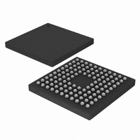
EFM32G890F64 Energy Micro, EFM32G890F64 Datasheet - Page 121

EFM32G890F64
Manufacturer Part Number
EFM32G890F64
Description
MCU 32BIT 64KB FLASH 112-BGA
Manufacturer
Energy Micro
Series
Geckor
Datasheets
1.EFM32-G890F128-SK.pdf
(70 pages)
2.EFM32-G890F128-SK.pdf
(10 pages)
3.EFM32G200F16.pdf
(463 pages)
4.EFM32G200F16.pdf
(136 pages)
Specifications of EFM32G890F64
Core Processor
ARM® Cortex-M3™
Core Size
32-Bit
Speed
32MHz
Connectivity
EBI/EMI, I²C, IrDA, SmartCard, SPI, UART/USART
Peripherals
Brown-out Detect/Reset, DMA, LCD, POR, PWM, WDT
Number Of I /o
90
Program Memory Size
64KB (64K x 8)
Program Memory Type
FLASH
Ram Size
16K x 8
Voltage - Supply (vcc/vdd)
1.8 V ~ 3.8 V
Data Converters
A/D 8x12b, D/A 2x12b
Oscillator Type
External
Operating Temperature
-40°C ~ 85°C
Package / Case
112-LFBGA
Processor Series
EFM32G890
Core
ARM Cortex-M3
Data Bus Width
32 bit
Data Ram Size
16 KB
Interface Type
I2C, UART
Maximum Clock Frequency
32 MHz
Number Of Programmable I/os
90
Number Of Timers
3
Operating Supply Voltage
1.8 V to 3.8 V
Maximum Operating Temperature
+ 85 C
Mounting Style
SMD/SMT
Minimum Operating Temperature
- 40 C
Lead Free Status / RoHS Status
Lead free / RoHS Compliant
Eeprom Size
-
Lead Free Status / Rohs Status
Details
Available stocks
Company
Part Number
Manufacturer
Quantity
Price
4.5.8.2 Updating an MPU region using multi-word writes
2011-02-04 - d0002_Rev1.00
; R1 = region number
; R2 = size/enable
; R3 = attributes
; R4 = address
LDR R0,=MPU_RNR
STR R1, [R0, #0x0]
BIC R2, R2, #1
STRH R2, [R0, #0x8]
STR R4, [R0, #0x4]
STRH R3, [R0, #0xA]
ORR R2, #1
STRH R2, [R0, #0x8]
Software must use memory barrier instructions:
• before MPU setup if there might be outstanding memory transfers, such as buffered writes, that might
• after MPU setup if it includes memory transfers that must use the new MPU settings.
However, memory barrier instructions are not required if the MPU setup process starts by entering an
exception handler, or is followed by an exception return, because the exception entry and exception
return mechanism cause memory barrier behavior.
Software does not need any memory barrier instructions during MPU setup, because it accesses the
MPU through the PPB, which is a Strongly-Ordered memory region.
For example, if you want all of the memory access behavior to take effect immediately after the
programming sequence, use a DSB instruction and an ISB instruction. A DSB is required after changing
MPU settings, such as at the end of context switch. An ISB is required if the code that programs the
MPU region or regions is entered using a branch or call. If the programming sequence is entered using
a return from exception, or by taking an exception, then you do not require an ISB.
You can program directly using multi-word writes, depending on how the information is divided. Consider
the following reprogramming:
; R1 = region number
; R2 = address
be affected by the change in MPU settings
; 0xE000ED98, MPU region number register
; Region Number
; Disable
; Region Size and Enable
; Region Base Address
; Region Attribute
; Enable
; Region Size and Enable
...the world's most energy friendly microcontrollers
121
www.energymicro.com


