EA STARTEDIP240J ELECTRONIC ASSEMBLY, EA STARTEDIP240J Datasheet - Page 4
EA STARTEDIP240J
Manufacturer Part Number
EA STARTEDIP240J
Description
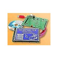
LCD Graphic Display Modules & Accessories Starter/Demoboard w/Touch USB prog
Manufacturer
ELECTRONIC ASSEMBLY
Datasheet
1.EA_EDIP240J-7LATP.pdf
(21 pages)
Specifications of EA STARTEDIP240J
Fluid Type
FSTN Positive
Module Size (w X H X T)
96 mm x 60.4 mm x 10.8 mm
Viewing Area (w X H)
91.18 mm x 56.3 mm
Backlighting
Black / White
Background Color
White
Operating Temperature Range
- 20 C to + 70 C
Attached Touch Screen
Yes
Interface
RS-232, I2C BUS, or SPI BUS
Lead Free Status / RoHS Status
Lead free / RoHS Compliant


EA eDIP240-7
Page 4
RS-232/RS-422 INTERFACE
Wiring the display as shown below selects the RS-232/RS-422 interface. The pin assignment is
shown in the table on the right.
The RxD and TxD lines have a 5V
CMOS line level. If “genuine” RS-
232 levels are required (e.g. for
direct connection to a PC), an
external level converter such as the
ICL232 is necessary.
BAUD RATES
The baud rate is set with pins 6, 7 and 8 (Baud0 through 2). The data
format is set permanently to 8 data bits, 1 stop bit, no parity.
RTS/CTS handshaking lines are not required. The integrated software
protocol takes on the necessary control functions (see pages 8 and 9).
Pin
10
11
12
13
14
15
16
17 EEP_SDA Bidir. Serial Data Line for int. EEPROM
18 EEP_SCL
19 EEP_WP
20
1
2
3
4
5
6
7
8
9
Symbol
BAUD0
BAUD1
BAUD2
RESET
EN485
VOUT
ADR0
DPOM
ADR1
ADR2
VADJ
BUZZ
SBUF
TEST
GND
VDD
RxD
TxD
In/Out Function
Out
Out
Out
Out
Out
Out
IN
In
In
In
In
In
In
In
In
In
In
-
-
-
Application example
Ground Potential for logic (0V)
Power supply for logic (+5V)
Operating voltage for LC driving
(input)
Output voltage for LC driving
L: Reset
Baud Rate 0
Baud Rate 1
Baud Rate 2
Address 0 for RS-485 (V1.3 or later)
Receive Data
Transmit Data
Transmit Enable for RS-485 driver
L: disable Power-On-Macro
do not connect for normal operation
Address 1 for RS-485 (V1.3 or later)
Address 2 for RS-485 (V1.3 or later)
Buzzer output
Serial Clock Line for int. EEPROM
H: Write Protect for int. EEPROM
open-drain with internal pullup 20..50k
IN (Power-On) L: Testmode
OUT L: data in sendbuffer
Pinout eDIP240-7
RS-232 / RS-422 mode
Note:
The pins BAUD 0 to 2, ADR 0 to 2, WUP,
DPROT and TEST/SBUF have an internal
pullup, which is why only the LO level
(0=GND) is to be actively applied. These
pins must be left open for a Hi level.
For RS232 operation (without
addressing) the pins ADR 0 to ADR 2
must be left open.
On pin 20 (SBUF) the display indicates
with a low level that data is ready to be
retrieved from the internal send buffer.
The line can be connected to an interrupt
input of the host system, for example.
Pin Symbol Function
21
22
23
24
25
26
27
28
29
30
31
32
33
34
35
36
37
38
39
40
Baud0 Baud1 Baud2
Specifications may be changed without
prior notice. Printing error reserved
0
1
0
1
0
1
0
1
N.C.
N.C.
N.C.
N.C.
N.C.
N.C.
N.C.
N.C.
N.C.
N.C.
N.C.
N.C.
N.C.
N.C.
N.C.
N.C.
N.C.
N.C.
N.C.
N.C.
not connected
not connected
not connected
not connected
not connected
not connected
not connected
not connected
not connected
not connected
not connected
not connected
not connected
not connected
not connected
not connected
not connected
not connected
not connected
not connected
0
0
1
1
0
0
1
1
Baud rates
0
0
0
0
1
1
1
1
Data format
115200
19200
38400
57600
8,N,1
1200
2400
4800
9600
Related parts for EA STARTEDIP240J
Image
Part Number
Description
Manufacturer
Datasheet
Request
R

Part Number:
Description:
Display Modules & Development Tools Starter/Demoboard Windows USB For DOGM
Manufacturer:
ELECTRONIC ASSEMBLY

Part Number:
Description:
Display Modules & Development Tools Starter/Demoboard DOGM/ Windows USB
Manufacturer:
ELECTRONIC ASSEMBLY
Datasheet:

Part Number:
Description:
LCD Character Display Modules 4x20 Yellow/Green RS-232 Interface
Manufacturer:
ELECTRONIC ASSEMBLY
Part Number:
Description:
LCD Character Display Modules 4x20 Blue-White RS-232 Interface
Manufacturer:
ELECTRONIC ASSEMBLY
Part Number:
Description:
LCD Character Display Modules 2x16 Yellow/Green RS-232 Interface
Manufacturer:
ELECTRONIC ASSEMBLY

Part Number:
Description:
LCD Character Display Modules STN(+) Reflective Yel/Grn Background
Manufacturer:
ELECTRONIC ASSEMBLY
Datasheet:

Part Number:
Description:
LCD Character Display Modules STN(-) Transmissive Blue Background
Manufacturer:
ELECTRONIC ASSEMBLY
Datasheet:

Part Number:
Description:
LCD Character Display Modules FSTN(-) Transmissive Black Background
Manufacturer:
ELECTRONIC ASSEMBLY
Datasheet:

Part Number:
Description:
LCD Character Display Modules Yel/Green Contrast Yl/Grn LED Backlight
Manufacturer:
ELECTRONIC ASSEMBLY
Datasheet:

Part Number:
Description:
LCD Character Display Modules STN(+) Transmissive Yel/Grn Background
Manufacturer:
ELECTRONIC ASSEMBLY
Datasheet:

Part Number:
Description:
LCD Touch Panels Touchpanel Analog for DOGM128-6
Manufacturer:
ELECTRONIC ASSEMBLY
Datasheet:
Part Number:
Description:
LCD Touch Panels Touchpanel Analog For DOGS102
Manufacturer:
ELECTRONIC ASSEMBLY
Datasheet:
Part Number:
Description:
LCD Touch Panels Touchpanel Analog For DOGXL160
Manufacturer:
ELECTRONIC ASSEMBLY
Datasheet:
Part Number:
Description:
LCD Touch Panels Touchpanel Analog For DOG-L128-6
Manufacturer:
ELECTRONIC ASSEMBLY
Datasheet:

Part Number:
Description:
LED Displays Bezel 017-xx Series 75.0x24.2/ 91.0x36.4
Manufacturer:
ELECTRONIC ASSEMBLY
Datasheet: