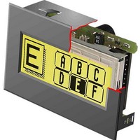
EA KIT120-5LEDTK ELECTRONIC ASSEMBLY, EA KIT120-5LEDTK Datasheet - Page 4

EA KIT120-5LEDTK
Manufacturer Part Number
EA KIT120-5LEDTK
Description
LCD Graphic Display Modules & Accessories Yel/Green Backlight RS-232 Snap-In Kit
Manufacturer
ELECTRONIC ASSEMBLY
Datasheet
1.EA_KIT120-5LEDTK.pdf
(20 pages)
Specifications of EA KIT120-5LEDTK
Pixel Density
120 x 32
Module Size (w X H X T)
70 mm x 45 mm x 24 mm
Viewing Area (w X H)
56.4 mm x 20.8 mm
Backlighting
LED
Background Color
Yellow, Green
Operating Temperature Range
- 20 C to + 70 C
Attached Touch Screen
Yes
Product
Graphic LCD Module
Style
LCD Graphic Display
Interface
RS-232
Lead Free Status / RoHS Status
Lead free / RoHS Compliant
EA KIT120-5
SUPPLY VOLTAGE / RS-232 CONNECTION
In the standard model, the supply voltage of +5V is fed in via screw-
type terminal J1. Alternatively, the 5V supply can be connected via
J3 (pin 1 and pin 10).
Note: It is imperative that the polarity is correct.
configure it. To do this, you have to connect the KIT to COM1 or
COM2 and pass the new baud rate as a parameter (e.g. KITBAUD
19200). The following baud rates can be set: 1200, 2400, 4800,
WRITE PROTECTION FOR MACRO PROGRAMMING
Closing solder strap LB1 (WP-VDD connection) prevents the programmed macros, images and fonts
from being overwritten inadvertently. The baud rate can then no longer be set either.
INPUTS AND OUTPUTS
The KIT120 is supplied with 5 digital inputs and 5 outputs (5V CMOS level, non-isolated). The connection
is made at the 20-pin connector J3.
5 outputs: Each line can be controlled by means of the „ESC Y W“ command. The maximum current per
line is 6mA.
5 inputs: The inputs can be queried and evaluated („ESC Y R“) directly via the serial interface. Each
change of logic level (0V or 5V) at the inputs can start an internal port macro. When the 5 lines are
combined, 32 port macros can be addressed. Each of these port macros can change the contents of the
screen or switch an output. This allows a wide range of control tasks to be carried out. To create the port
macros, you need a PC and the floppy disk EA DISK240. You will find a more detailed description of this
on page 6. Automatic poll querying can be disabled by means of the „ESC Y A 0“ command.
Note: The logic circuitry is designed for slow operations; in other words, more than 3 changes per second
cannot be easily executed. If an input is open, this is evaluated as high (approx. 50 kOhm pullup).
*)
4
Pin Symbol In/Out Function
1
2
3
4
5
6
7
also available on the Internet at http://www.lcd-module.de/deu/disk/disk240.zip
TXD5
RXD5
RTS5
CTS5
5V RS-232 Solder Pads J5
VDD
GND
WP
Out
Out
In
In
In
EEprom Write Protection
+5V Power Supply
0V Ground
Transmit data CMOS
Receive data CMOS
Request To Send CMOS
Clear To send CMOS
9600, 19200, 38400, 56700 and 115200.
Please note that the internal data buffer is only 32 bytes. The RTS
handshake line must therefore be queried (+10V level: data can be
accepted; -10V level: display is busy). The data format is set
permanently to 8 data bits, 1 stop bit, no parity.
If the RS-232 data is fed in to J5 at the 5V level, solder straps LB2 and
LB3 must be opened.
The 20-pin connector J3
contains the connection for
the RS-232 interface
(±12V) and the 5 inputs and
outputs (5V C-MOS level).
The baud rate is set in the
factory to 9600. You can
use
KITBAUD.EXE (available
on
EA DISK240
the
program
*)
)
to
Pin Symbol In/Out
10
11
12
13
14
15
16
17
18
19
20
1
2
3
4
5
6
7
8
9
RS-232 / PORT Box Header J3
OUT1
OUT2
OUT3
OUT4
OUT5
DCD
VDD
DSR
DTR
GND
CTS
RxD
RTS
TxD
IN1
IN2
IN3
IN4
IN5
-
Out Transmit Data
Out Request To Send
Out CMOS Output 1
Out CMOS Output 2
Out CMOS Output 3
Out CMOS Output 4
Out CMOS Output 5
In
In
In
In
In
In
In
-
-
-
-
-
-
+ 5V PowerSupply
Bridge to DTR
Bridge to DTR
Clear To Send
Receive Data
see Pin 2, Pin 3
NC
0V Ground
CMOS Input 1
CMOS Input 2
CMOS Input 3
CMOS Input 4
CMOS Input 5
Function
EA KV24-9B10
socket
10-pin
Pin
IDC
1
6
2
7
3
8
4
9
5
SUB-D
9-pin
Pin
10
1
2
3
4
5
6
7
8
9


