TSOP75456WTR Vishay, TSOP75456WTR Datasheet - Page 6
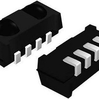
TSOP75456WTR
Manufacturer Part Number
TSOP75456WTR
Description
Infrared Receivers IR SENSOR IC 56KHZ
Manufacturer
Vishay
Datasheet
1.TSOP75256WTR.pdf
(12 pages)
Specifications of TSOP75456WTR
Carrier Frequency
56 KHz
Supply Current
0.35 mA
Beam Angle
75 deg
Mounting Style
SMD/SMT
Transmission Distance
30 m
Output Current
5 mA
Operating Voltage
2.5 V to 5.5 V
Power Dissipation
10 mW
Maximum Operating Temperature
+ 85 C
Minimum Operating Temperature
- 25 C
Transmission Range
30m
Directivity
75°
Supply Voltage Range
2.5V To 5.5V
Opto Case Style
SMD
Operating Temperature Range
-25°C To +85°C
Lead Free Status / RoHS Status
Lead free / RoHS Compliant
Lead Free Status / RoHS Status
Lead free / RoHS Compliant, Lead free / RoHS Compliant
Available stocks
Company
Part Number
Manufacturer
Quantity
Price


TSOP752..W, TSOP754..W
Vishay Semiconductors
PACKAGE DIMENSIONS in millimeters
ASSEMBLY INSTRUCTIONS
Reflow Soldering
• Reflow soldering must be done within 72 h while stored
• Set the furnace temperatures for pre-heating and heating
• Handling after reflow should be done only after the work
www.vishay.com
6
THE PRODUCT DESCRIBED HEREIN AND THIS DATASHEET ARE SUBJECT TO SPECIFIC DISCLAIMERS, SET FORTH AT
under a max. temperature of 30 °C, 60 % RH after
opening the dry pack envelope
in accordance with the reflow temperature profile as
shown in the diagram. Excercise extreme care to keep the
maximum temperature below 260 °C. The temperature
shown in the profile means the temperature at the device
surface. Since there is a temperature difference between
the component and the circuit board, it should be verified
that the temperature of the device is accurately being
measured
surface has been cooled off
mold residue
Drawing-No.: 6.550-5300.01-4
Issue: 3; 23.03.2011
21582
Tool separation line
0.5 ± 0.1
(4 x)
IR Receiver Modules for Remote
This datasheet is subject to change without notice.
3 x 1.27
Marking area
6.6 ± 0.1
(3.25)
(2.2)
6.8
(3 x)
1.27
=
(0.635)
3.81
Control Systems
Pick and place area
Manual Soldering
• Use a soldering iron of 25 W or less. Adjust the
• Finish soldering within 3 s
• Handle products only after the temperature has cooled off
temperature of the soldering iron below 300 °C
mold residue
center of
sensitive area
Not indicated tolerances ± 0.15
1.27
Proposed hole layout
from component side
(for reference only)
(1)
0.8
technical drawings
according to DIN
specifications
3 x 1.27 = 3.81
2.35
www.vishay.com/doc?91000
Document Number: 81598
Rev. 1.4, 24-Mar-11
Related parts for TSOP75456WTR
Image
Part Number
Description
Manufacturer
Datasheet
Request
R

Part Number:
Description:
357-036-542-201 CARDEDGE 36POS DL .156 BLK LOPRO
Manufacturer:
Vishay
Datasheet:
Part Number:
Description:
357-036-542-201 CARDEDGE 36POS DL .156 BLK LOPRO
Manufacturer:
Vishay
Datasheet:
Part Number:
Description:
357-036-542-201 CARDEDGE 36POS DL .156 BLK LOPRO
Manufacturer:
Vishay
Datasheet:
Part Number:
Description:
357-036-542-201 CARDEDGE 36POS DL .156 BLK LOPRO
Manufacturer:
Vishay
Datasheet:
Part Number:
Description:
357-036-542-201 CARDEDGE 36POS DL .156 BLK LOPRO
Manufacturer:
Vishay
Datasheet:
Part Number:
Description:
357-036-542-201 CARDEDGE 36POS DL .156 BLK LOPRO
Manufacturer:
Vishay
Datasheet:
Part Number:
Description:
357-036-542-201 CARDEDGE 36POS DL .156 BLK LOPRO
Manufacturer:
Vishay
Datasheet:
Part Number:
Description:
357-036-542-201 CARDEDGE 36POS DL .156 BLK LOPRO
Manufacturer:
Vishay
Datasheet:
Part Number:
Description:
357-036-542-201 CARDEDGE 36POS DL .156 BLK LOPRO
Manufacturer:
Vishay
Datasheet:
Part Number:
Description:
357-036-542-201 CARDEDGE 36POS DL .156 BLK LOPRO
Manufacturer:
Vishay
Datasheet:
Part Number:
Description:
357-036-542-201 CARDEDGE 36POS DL .156 BLK LOPRO
Manufacturer:
Vishay
Datasheet:
Part Number:
Description:
357-036-542-201 CARDEDGE 36POS DL .156 BLK LOPRO
Manufacturer:
Vishay
Datasheet:
Part Number:
Description:
357-036-542-201 CARDEDGE 36POS DL .156 BLK LOPRO
Manufacturer:
Vishay
Datasheet:
Part Number:
Description:
357-036-542-201 CARDEDGE 36POS DL .156 BLK LOPRO
Manufacturer:
Vishay
Datasheet:
Part Number:
Description:
357-036-542-201 CARDEDGE 36POS DL .156 BLK LOPRO
Manufacturer:
Vishay
Datasheet: