TSOP4136 Vishay, TSOP4136 Datasheet

Infrared Receivers 4.5-5.5V 36kHz

TSOP4136

Manufacturer Part Number
TSOP4136
Description
Infrared Receivers 4.5-5.5V 36kHz
Manufacturer
Vishay
Datasheet

Specifications of TSOP4136

Carrier Frequency
36 KHz
Supply Current
0.85 mA
Beam Angle
45 deg
Data Transmission Rate
4000 bits/s
Mounting Style
Through Hole
Transmission Distance
45 m
Viewing Angle
45 deg
Output Current
5 mA
Operating Voltage
2.7 V to 5.5 V
Power Dissipation
10 mW
Maximum Operating Temperature
+ 85 C
Minimum Operating Temperature
- 25 C
Transmission Range
45m
Directivity
45°
Supply Voltage Range
2.7V To 5.5V
Opto Case Style
Through Hole
Operating Temperature Range
-25°C To +85°C
Operating Supply Voltage (typ)
3.3/5V
Operating Supply Voltage (min)
2.7V
Operating Supply Voltage (max)
5.5V
Mounting
Through Hole
Pin Count
3
Operating Temperature Classification
Commercial
Lead Free Status / RoHS Status
Lead free / RoHS Compliant
Lead Free Status / RoHS Status
Lead free / RoHS Compliant, Lead free / RoHS Compliant

Available stocks

Company
Part Number
Manufacturer
Quantity
Price
Part Number:
TSOP4136
Manufacturer:
VISHAY
Quantity:
2 000
Part Number:
TSOP4136/TSOP4140
Manufacturer:
NEC
Quantity:
10 000
Part Number:
TSOP4136LL1
Manufacturer:
LITON
Quantity:
9 530
Part Number:
TSOP4136SS1BS12
Manufacturer:
VISHAY
Quantity:
2 025
Part Number:
TSOP4136ST1
Manufacturer:
VISHAY
Quantity:
10 907
MECHANICAL DATA
Pinning for TSOP41.., TSOP43..:
1 = OUT, 2 = GND, 3 = V
Pinning for TSOP21.., TSOP23..:
1 = OUT, 2 = V
BLOCK DIAGRAM
** Please see document “Vishay Material Category Policy”:
Document Number: 82135
Rev. 2.8, 04-Feb-11
16833_14
PARTS TABLE
CARRIER
FREQUENCY
30 kHz
33 kHz
36 kHz
38 kHz
40 kHz
56 kHz
PIN
Input
1
2
S
IR Receiver Modules for Remote Control Systems
, 3 = GND
AGC
3
1 = OUT, 2 = GND, 3 = V
Control circuit
Band
pass
S
SHORT BURST AND HIGH DATA RATE
TSOP4130
TSOP4133
TSOP4136
TSOP4138
TSOP4140
TSOP4156
Demo-
dulator
33 kΩ
16672
(AGC1)
S
1 = OUT, 2 = V
TSOP21.., TSOP23.., TSOP41.., TSOP43..
3
2
1
www.vishay.com/doc?99902
TSOP2130
TSOP2133
TSOP2136
TSOP2138
TSOP2140
TSOP2156
S
, 3 = GND
FEATURES
• Low supply current
• Photo detector and preamplifier in one
• Internal filter for PCM frequency
• Improved shielding against EMI
• Supply voltage: 2.7 V to 5.5 V
• Improved immunity against ambient light
• Insensitive to supply voltage ripple and noise
• Compliant to RoHS Directive 2002/95/EC and
DESCRIPTION
These products are miniaturized receivers for infrared
remote control systems. A PIN diode and a preamplifier are
assembled on a lead frame, the epoxy package acts as an
IR filter.
The demodulated output signal can directly be decoded by
a microprocessor. The main benefit of the TSOP41..,
TSOP21.. is the compatibility to all IR remote control data
formats. The TSOP43.., TSOP23.. are optimized to better
suppress spurious pulses from fluorescent lamps, LCD TVs
or plasma displays.
This component has not been qualified according to
automotive specifications.
APPLICATION CIRCUIT
PINNING
17170_7
The external components R
to improve the robustness against electrical overstress
(typical values are R
The output voltage V
below 1 V by the external circuit.
The capacitive load at the output should be less than 2 nF.
package
in accordance to WEEE 2002/96/EC
Transmitter
TSALxxxx
with
1 = OUT, 2 = GND, 3 = V
NOISY ENVIROMENTS AND SHORT BURSTS
IR receiver
TSOP4330
TSOP4333
TSOP4336
TSOP4338
TSOP4340
TSOP4356
1
O
= 100 Ω, C
should not be pulled down to a level
Vishay Semiconductors
1
and C
GND
V
OUT
1
S
= 0.1 µF).
1
(AGC3)
S
are optional
C
1 = OUT, 2 = V
R
1
1
V
O
TSOP2330
TSOP2333
TSOP2336
TSOP2338
TSOP2340
TSOP2356
µC
www.vishay.com
GND
+ V
S
S
, 3 = GND
1

Related parts for TSOP4136

TSOP4136 Summary of contents

Page 1

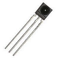
... OUT GND Pinning for TSOP21.., TSOP23..: 1 = OUT GND S PARTS TABLE SHORT BURST AND HIGH DATA RATE CARRIER FREQUENCY 1 = OUT GND kHz TSOP4130 33 kHz TSOP4133 36 kHz TSOP4136 38 kHz TSOP4138 40 kHz TSOP4140 56 kHz TSOP4156 BLOCK DIAGRAM 16833_14 Band Demo- Input AGC pass dulator PIN Control circuit ** Please see document “ ...

Page 2

... TSOP21.., TSOP23.., TSOP41.., TSOP43.. Vishay Semiconductors ABSOLUTE MAXIMUM RATINGS PARAMETER Supply voltage Supply current Output voltage Voltage at output to supply Output current Junction temperature Storage temperature range Operating temperature range Power consumption Soldering temperature Note • Stresses beyond those listed under “Absolute Maximum Ratings” may cause permanent damage to the device. This is a stress rating only and functional operation of the device at these or any other conditions beyond those indicated in the operational sections of this specification is not implied ...

Page 3

... Control Systems t 94 8134 t t off 21393_1 off 21394_1 Fig Sensitivity vs. Supply Voltage Disturbances 1.3 20747 Vishay Semiconductors 5 Correlation with Ambient Light Sources: 4 W/m = 1.4 kLx (Std. illum 2855 W/m = 8.2.kLx (Daylight 5900 K) 3.5 3 2.5 2 1.5 Wavelength of Ambient 1 Illumination: λ = 950 nm ...

Page 4

... TSOP21.., TSOP23.., TSOP41.., TSOP43.. Vishay Semiconductors 1.0 0.9 0.8 0.7 TSOP41.. TSOP21.. 0.6 0.5 0.4 TSOP43.. 0.3 TSOP23.. 0.2 0 mW/m² 21590-10 Burst Length (Number of Cycles/Burst) Fig Max. Envelope Duty Cycle vs. Burst Length 0.3 0.25 0.2 0.15 0.1 0. Ambient Temperature (°C) ...

Page 5

... TSOP41.., TSOP21.. 6 cycles/burst cycles  10 cycles 70 cycles > 1.1 x burst length 2000 yes yes yes yes yes yes yes Common disturbance signals are supressed (example: signal pattern of fig. 14) Vishay Semiconductors Time (ms) with Low Modulation Time (ms) with High Modulation TSOP43.., TSOP23.. 6 cycles/burst cycles  ...

Page 6

... TSOP21.., TSOP23.., TSOP41.., TSOP43.. Vishay Semiconductors PACKAGE DIMENSIONS in millimeters 0.7 max. 2.54 nom. marking area Drawing-No.: 6.550-5169.01-4 Issue: 9; 03.11.10 13655 www.vishay.com 6 IR Receiver Modules for Remote Control Systems 6 0.85 max. 0.89 2.54 nom. Not indicated tolerances ± 0.2 R 2.5 3.9 0.5 max. ...

Page 7

... Vishay product could result in personal injury or death. Customers using or selling Vishay products not expressly indicated for use in such applications their own risk and agree to fully indemnify and hold Vishay and its distributors harmless from and against any and all claims, liabilities, expenses and damages arising or resulting in connection with such use or sale, including attorneys fees, even if such claim alleges that Vishay or its distributor was negligent regarding the design or manufacture of the part ...

Related keywords