TFDU6103-TR3 Vishay, TFDU6103-TR3 Datasheet - Page 5
TFDU6103-TR3
Manufacturer Part Number
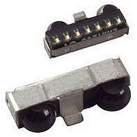
TFDU6103-TR3
Description
Infrared Transceivers SIR 115.2kbits Side View
Manufacturer
Vishay
Type
Fastr
Datasheet
1.TFDU6103-TR3.pdf
(13 pages)
Specifications of TFDU6103-TR3
Data Transmission Rate
4000 Kbits/s
Input Current
10 mA
Mounting Style
SMD/SMT
Power Dissipation
500 mW
Wavelength
886 nm
Continual Data Transmission
4 Mbit/s
Transmission Distance
1 m
Radiant Intensity
170 mW/sr
Half Intensity Angle Degrees
48 deg
Pulse Width
2.1 us
Maximum Rise Time
40 ns
Maximum Fall Time
40 ns
Led Supply Voltage
- 0.5 V to 6.5 V
Maximum Forward Current
10 mA
Operating Voltage
2.4 V to 5.5 V
Maximum Operating Temperature
+ 85 C
Minimum Operating Temperature
- 25 C
Dimensions
9.7 mm x 4.7 mm x 4 mm
Data Rate Max
4Mbps
Data Transmission Distance
1m
Peak Wavelength
886nm
Supply Current
2mA
Supply Voltage Range
2.4V To 5.5V
Operating Temperature Range
-25°C To +85°C
Msl
MSL 4 - 72 Hours
Data Rate
4Mbps
Angle Of Half Sensitivity
48°
Communication Distance
100
Package Type
Ultra Small Profile
Fall Time
40ns
Rise Time
40ns
Operating Supply Voltage (typ)
2.5/3.3/5V
Operating Supply Voltage (min)
2.4V
Operating Supply Voltage (max)
5.5V
Mounting
Surface Mount
Pin Count
8
Operating Temp Range
-25C to 85C
Operating Temperature Classification
Commercial
Idle Current, Typ @ 25° C
2mA
Link Range, Low Power
1m
Operating Temperature
-25°C ~ 85°C
Orientation
Side View
Shutdown
*
Size
9.7mm x 4.7mm x 4mm
Standards
IrPHY 1.4
Supply Voltage
2.4 V ~ 5.5 V
Lead Free Status / RoHS Status
Lead free / RoHS Compliant
Lead Free Status / RoHS Status
Lead free / RoHS Compliant, Lead free / RoHS Compliant
Available stocks
Company
Part Number
Manufacturer
Quantity
Price
Company:

Part Number:
TFDU6103-TR3
Manufacturer:
ST
Quantity:
1 001
Company:
Part Number:
TFDU6103-TR3
Manufacturer:
VISHAY
Quantity:
6 580


Notes
(1)
(2)
(3)
(4)
(5)
(6)
(7)
Document Number: 81211
Rev. 1.4, 29-Jul-09
OPTOELECTRONIC CHARACTERISTICS
PARAMETER
TRANSMITTER
IRED operating current,
switched current limiter
Output pulse width limitation
Output leakage IRED current
Output radiant intensity,
see figure 1, recommended
application circuit
Output radiant intensity,
see figure 1, recommended
application circuit
Output radiant intensity
Output radiant intensity, angle
of half intensity
Peak - emission wavelength
Spectral bandwidth
Optical rise time,
Optical fall time
Optical output pulse duration
Optical overshoot
T
transmission header. The data given here are valid 5 µs after starting the preamble.
Typical values are for design aid only, not guaranteed nor subject to production testing.
This parameter reflects the backlight test of the IrDA physical layer specification to guarantee immunity against light from fluorescent lamps.
IrDA sensitivity definition: minimum irradiance E
the source is operating at the minimum intensity in angular range into the minimum half-angular range at the maximum link length.
Maximum irradiance E
intensity in angular range at minimum link length must not cause receiver overdrive distortion and possible related link errors. If placed at the
active output interface reference plane of the transmitter, the receiver must meet its bit error ratio (BER) specification. For more definitions
see the document “Symbols and Terminology” on the Vishay website
Retriggering once during applied optical pulse may occur.
Maximum value is given by eye safety class 1, IEC 60825-1, simplified method.
Due to this wavelength restriction compared to the IrDA spec of 850 nm to 900 nm the transmitter is able to operate as source for the standard
remote control applications with codes as e.g. Philips RC5/RC6
the RC range to be covered is in the range from 8 m to 12 m, provided that state of the art remote control receivers are used.
amb
= 25 °C, V
CC
= 2.4 V to 5.5 V unless otherwise noted. All timing data measured with 4 Mbit/s are measured using the IrDA FIR
e
Fast Infrared Transceiver Module (FIR, 4 Mbit/s)
in angular range, power per unit area. The optical delivered to the detector by a source operating at the maximum
irdasupportAM@vishay.com, irdasupportAP@vishay.com,
(7)
For technical questions within your region, please contact one of the following:
Note: no external current limiting resistor is needed
TXD = low or SD = high (receiver is inactive as long
Input pulse width 217 ns, 1.152 Mbit/s
Input pulse width 20 µs < t < 150 µs
for 2.4 V to 5.5 V Operation
Input pulse width 125 ns, 4 Mbit/s
Input pulse width 250 ns, 4 Mbit/s
TXD = high, SD = low, R1 = 1
V
TXD = high, SD = low, R1 = 1
CC
Input pulse width t 150 µs
V
Input pulse width t < 20 µs
V
CC
= V
CC1
TEST CONDITIONS
V
= V
CC1
e
IRED
in angular range, power per unit area. The receiver must meet the BER specification while
= 3.3 V, = 0°, 15°
as SD = high)
IRED
= V
= 3.3 V, = 0°, 15°
for
CC2
= 3.3 V, = 0°
= 3.3 V
(1)
®
or RECS 80. When operated under IrDA full range conditions (125 mW/sr)
irdasupportEU@vishay.com
SYMBOL
t
pw_lim
I
t
IRED
ropt
t
t
t
t
t
t
fopt
I
opt
opt
opt
pw
pw
I
I
I
D
e
e
e
p
,
Vishay Semiconductors
MIN.
330
110
100
875
207
117
242
18
- 1
10
TYP.
± 24
440
170
130
886
217
125
250
45
t
TFDU6103
468
468
MAX.
0.04
600
150
150
900
227
133
258
40
25
1
www.vishay.com
(6)
(6)
mW/sr
mW/sr
mW/sr
UNIT
deg
mA
nm
nm
µA
µs
µs
µs
ns
ns
ns
ns
%
5
Related parts for TFDU6103-TR3
Image
Part Number
Description
Manufacturer
Datasheet
Request
R

Part Number:
Description:
Manufacturer:
Vishay Semiconductors
Datasheet:

Part Number:
Description:
Infrared Transceivers SIR 115.2kbits Top View
Manufacturer:
Vishay
Datasheet:

Part Number:
Description:
357-036-542-201 CARDEDGE 36POS DL .156 BLK LOPRO
Manufacturer:
Vishay
Datasheet:
Part Number:
Description:
357-036-542-201 CARDEDGE 36POS DL .156 BLK LOPRO
Manufacturer:
Vishay
Datasheet:
Part Number:
Description:
357-036-542-201 CARDEDGE 36POS DL .156 BLK LOPRO
Manufacturer:
Vishay
Datasheet:
Part Number:
Description:
357-036-542-201 CARDEDGE 36POS DL .156 BLK LOPRO
Manufacturer:
Vishay
Datasheet:
Part Number:
Description:
357-036-542-201 CARDEDGE 36POS DL .156 BLK LOPRO
Manufacturer:
Vishay
Datasheet:
Part Number:
Description:
357-036-542-201 CARDEDGE 36POS DL .156 BLK LOPRO
Manufacturer:
Vishay
Datasheet:
Part Number:
Description:
357-036-542-201 CARDEDGE 36POS DL .156 BLK LOPRO
Manufacturer:
Vishay
Datasheet:
Part Number:
Description:
357-036-542-201 CARDEDGE 36POS DL .156 BLK LOPRO
Manufacturer:
Vishay
Datasheet:
Part Number:
Description:
357-036-542-201 CARDEDGE 36POS DL .156 BLK LOPRO
Manufacturer:
Vishay
Datasheet:
Part Number:
Description:
357-036-542-201 CARDEDGE 36POS DL .156 BLK LOPRO
Manufacturer:
Vishay
Datasheet:
Part Number:
Description:
357-036-542-201 CARDEDGE 36POS DL .156 BLK LOPRO
Manufacturer:
Vishay
Datasheet:
Part Number:
Description:
357-036-542-201 CARDEDGE 36POS DL .156 BLK LOPRO
Manufacturer:
Vishay
Datasheet:
Part Number:
Description:
357-036-542-201 CARDEDGE 36POS DL .156 BLK LOPRO
Manufacturer:
Vishay
Datasheet: