DL100-7-PCBA3 Pacific Silicon Sensor, DL100-7-PCBA3 Datasheet

Photodiodes duall pos sensing w/preamp circuitry

DL100-7-PCBA3

Manufacturer Part Number
DL100-7-PCBA3
Description
Photodiodes duall pos sensing w/preamp circuitry
Manufacturer
Pacific Silicon Sensor
Type
Dual Axis Position Sensing Dioder
Datasheet

Specifications of DL100-7-PCBA3

Peak Wavelength
400 nm to 1100 nm
Package / Case
PCBA
Maximum Operating Temperature
+ 70 C
Minimum Operating Temperature
0 C
Lead Free Status / RoHS Status
Lead free / RoHS Compliant
Other names
10-018
The DL100-7PCBA3 is a dual axis position
sensing diode with sum and difference amplifiers. It
contains internal bias circuitry of 14.3 volts for the
position sensing diode, or the user can externally
apply a bias voltage. The board has a 9 pin
connector for easy hook up.
Outputs are bipolar voltage analogs of the X and Y
position of the light spot centroid, as well as the
total X current and the total Y current. The sum
outputs may be used to externally normalize the X
and Y difference outputs. By normalizing the X and
Y signals, they become independent of fluctuations
in light spot intensity.
SPECIFICATIONS
Power supply voltage V
max ± 18 volts; recommended ± 15 volts
Maximum ± output voltage: +V
Maximum output current limit: 25 ma
Maximum external bias: –V
+V
Maximum slew rate: 10 volts per microsecond
Theoretical noise: 15 nV Hz
Operating temperature: 0 to 70°C
–3db bandwidth: 257 kHz
Resolution (bias dependent): ≥ 0.5 µm
Linearity (bias dependent): ±1% of full scale
Maximum light intensity: 1.5 W/cm
See DL100-7PCBA application notes.
Version: 111306
DUAL AXIS PSD SUM AND DIFFERENCE AMPLIFIER SPECIFICATION
s
+10 volts
s
: min ± 10 volts;
s
–1/2
–10 volts;
s
–3; –V
2
s
+3
PIN
1
2
3
4
5
6
7
8
9
ALL DIMENSIONS IN INCHES
5700 Corsa Avenue, #105 • Westlake Village, CA 91362
Tel: (818) 706-3400 • Fax (818) 889-7053
Email: sales@pacific-sensor.com • www.pacific-sensor.com
CATHODE 1
CATHODE 2
FUNCTION
OPTIONAL –BIAS
OPTIONAL +BIAS
Y VOLTAGE OUT
X VOLTAGE OUT
ANODE SUM (Y)
CATHODE SUM (X)
+15 VOLTS
SIGNAL AND
POWER COMMON
–15 VOLTS
PSS-DL100-7-CER
OPTICAL
CENTER
0.56
ANODE 1
ANODE 2
0.13
0.13
Mechanical Outline
Block Diagram
0.76
1.65
1 2 3 4 5 6 7 8 9
SUM
SUM
DIFF
DIFF
–15V
+15V
AGND
+15V
–15V
J1
J2
Y
PINS 1-9 ON 0.100" CENTERS
0.13
– PHDBIAS (OPTIONAL) PIN 1
V(y) DIFFERENCE PIN 3
V(y) SUM PIN 5
+15V PIN 7
–15V PIN 9
ANALOG GROUND PIN 8
V(x) DIFFERENCE PIN 4
V(x) SUM PIN 6
+ PHDBIAS (OPTIONAL) PIN 2
0.10 DIA 2 PLACES
0.13
1.13
0.065
Page 1 of 3

Related parts for DL100-7-PCBA3

DL100-7-PCBA3 Summary of contents

Page 1

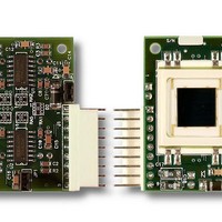
... DUAL AXIS PSD SUM AND DIFFERENCE AMPLIFIER SPECIFICATION The DL100-7PCBA3 is a dual axis position sensing diode with sum and difference amplifiers. It contains internal bias circuitry of 14.3 volts for the position sensing diode, or the user can externally apply a bias voltage. The board has a 9 pin connector for easy hook up ...

Page 2

... If the beam source changes intensity when the spot location is being sensed, then the output should be normalized using the sum signals available on the DL100-7PCBA3. Normalization is accomplished externally by dividing the location voltage by the sum voltage for the layer ( being measured. The DL100-7PCBA3 does not normalize the location output signals. ...

Page 3

... Resolution obtainable under specified conditions is 0.5µm or less. Speed of Response Increasing the PSD bias voltage will increase the speed of the DL100-7PCBA3. The internally created reverse bias of 14.3V is sufficient for most applications. As noted above, Pins 1 and 2 are provided to reduce or increase the 14.3V reverse bias, but biasing above 14 ...

Related keywords