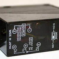
E3JM-R4M4-G Omron, E3JM-R4M4-G Datasheet

E3JM-R4M4-G
Specifications of E3JM-R4M4-G
Available stocks
Related parts for E3JM-R4M4-G
E3JM-R4M4-G Summary of contents
Page 1
... Order code tion Relay output method Terminal – E3JM-10M4-G-N block ON or OFF delay E3JM-10M4T-G-N E3JM-10S4T-G-N E3JM-10R4T-G-N (with 0 13.5) – E3JM-R4M4 OFF delay E3JM-R4M4T-G 0 – E3JM-DS70M4-G E3JM-DS70S4-G E3JM-DS70R4 OFF delay E3JM-DS70M4T-G E3JM-DS70S4T-G E3JM-DS70R4T-G 0 SSR output minus common plus common E3JM-10S4-G-N E3JM-10R4-G-N E3JM-R4S4-G ...
Page 2
... Model Quantity Remarks E39-R1 1 E39- E39-RS2 1 1 Quantity Remarks 1 Quantity Remarks 1 Slit each for Emitter (Seal-type long slit) and Receiver (2 Slits Can be used with the total ) Through-beam Model E3JM-10@4(T). Provided with the E3JM-R4@4(T). --- --- Provided with the E3JM Multi voltage photoelectric sensor ...
Page 3
... Iron Bracket Accessories Mounting Bracket (with screw), nut, terminal protection cover, one set of cable connection nuts, reflector (E39-R1: only for retro-reflective models), instruction manual Note: The timer cannot be disabled for Models with timer functions (E3JM-@@@4T). E3JM Retro-reflective with M.S.R. E3JM-10@4T E3JM-R4 (When using E39-R1) Opaque: 75-mm dia ...
Page 4
... SUS (Luster) Aluminum foil 6 (No luster on the back 100 120 140 160 180 200 220 1200 Side length of sensing object (mm) Excess Gain Ratio vs. Set Distance (Typical) Retro-reflective E3JM-R4@4(T) (When Using E39-R3) 1,000 Reflector: E39-R3 500 300 100 Operating level 1 0.5 0.3 0.1 ...
Page 5
... Dark-ON mode D·ON OFF E3JM DC SSR Output Models E3JM-@S4(T) Drive circuit Photo- Drive electric circuit Sensor Main circuit E3JM-@R4(T) Drive circuit Photo- electric Sensor Drive Main circuit circuit Models with Timer ON-delay Incident light Incident light No incident light No incident light ...
Page 6
... Switch for operating mode 6 Adjustment Through-beam Models For a E3JM with the timer function, the indicator will be lit when incident light is received while the mode is switched to Light-ON, and the indicator will be lit when light is interrupted while the mode is switched to Dark-ON. Move the Emitter and Receiver horizontally and vertically, and locate them to the center of the range in which the Receiver indi- cator is lit ...
Page 7
... Photoelectric Sensor is turned OFF ). 7 max. OFF-delay One-shot delay MODE MODE D·ON L·ON D·ON L·ON SW1 SW1 TIMER TIMER SW2 SW2 Only SW2 at "1." Only SW1 at "1," which overrides either setting of SW2. Terminal protection cover E3JM 7 ...
Page 8
... The E3JM will malfunction if installed in the following places. • Places where the E3JM is exposed to a dusty environment. • Places where corrosive gases are produced. • Places where the E3JM is directly exposed to water, oil, or chemicals. Dimensions Note 1. The operating mode switch and timer mode switch are located inside the cover. ...
Page 9
... Back side: ABS resin 11 Adhesive 25.4 34.8 Two, M3 19.3 22.5 2.6 Tape Reflectors (Order Separately) E39-RS1 35 10 Four, R1 Adhesive Materials: Acrylic E39-RS2 40 35 Four, R1 Materials: Acrylic E3JM 40.3 34 Two, 3.5 dia. 7 2.7 1.6 20 0.2 22.5 19.3 34.8 38 Two, M3 25.4 41.8 1 ...
Page 10
... The Netherlands Phone: +31 23 568 13 00 Fax: +31 23 568 13 88 www.industrial.omron.eu E3JM • Outdoor use, uses involving potential chemical contamination or electrical interference, or conditions or uses not described in this document. • Nuclear energy control systems, combustion systems, railroad sys- tems, aviation systems, medical equipment, amusement machines, vehicles, safety equipment, and installations subject to separate in- dustry or government regulations ...


