E3F2-R4C4 Omron, E3F2-R4C4 Datasheet - Page 8
E3F2-R4C4
Manufacturer Part Number
E3F2-R4C4
Description
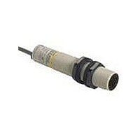
Industrial Photoelectric Sensors NPN RETRO 4M DC PREWIRED PLASTIC
Manufacturer
Omron
Type
Photoelectric Sensorr
Series
E3F2r
Specifications of E3F2-R4C4
Features
DC switching types with connectors
Maximum Operating Temperature
+ 55 C
Minimum Operating Temperature
- 25 C
Operating Supply Voltage
10 V to 30 V
Sensing Distance
4 mm to 100 mm
Output Configuration
NPN
Output Current
100mA
Sensor Output
NPN
Supply Voltage Range Dc
10V To 30V
Sensor Housing
Cylindrical
Sensor Input
Optical
Supply Voltage Max
240VAC
Sensing Range Max
4m
Sensing Method
Retroreflective, Polarized
Sensing Object
Mirror
Sensing Light
Red
Mounting Type
M18 Threaded Body, Nut
Current - Supply
30mA
Voltage - Supply
10 V ~ 30 V
Package / Case
Axial, Pre-Wired
Sensing Mode
Retroreflective
Rohs Compliant
Yes
Lead Free Status / RoHS Status
Lead free / RoHS Compliant
Lead Free Status / RoHS Status
Lead free / RoHS Compliant, Lead free / RoHS Compliant


Operation
Output Circuits
PNP Output
Note: Terminal numbers for connector type.
8
1
4
2
3
Model
E3F2-@B4-@
(except for
E3F2-LS10B4-@)
E3F2-LS10B4-@
XS2F-D42#-D80-#
XS2F-G42#-G80-#
Output transistor
status
–
ON when light is
incident.
(Light-ON)
ON when light is
interrupted.
(Dark-ON)
ON when light is
incident.
(Light-ON)
ON when light is
interrupted.
(Dark-ON)
Brown
White
Blue
Black
Timing chart
–
Incident
Interrupted
Output
indicator
(red)
Output
transistor
Load
(relay)
Incident
Interrupted
Output
indicator
(red)
Output
transistor
Load
(relay)
Incident
Interrupted
Output
indicator
(orange)
Output
transistor
Load
(relay)
Incident
Interrupted
Output
indicator
(orange)
Output
transistor
Load
(relay)
Operate
Release
Operate
Release
Operate
Release
Operate
Release
OFF
OFF
OFF
OFF
OFF
OFF
OFF
OFF
ON
ON
ON
ON
ON
ON
ON
ON
Structure of Sensor I/O Connector
Classification Wire color Connector
DC
Connection
method
–
Connect the
pink (Pin
and brown
(Pin
or open the
pink cord
(Pin
Connect the
pink (Pin
and blue
(Pin
Connect the
pink (Pin
and brown
(Pin
or open the
pink cord
(Pin
Connect the
pink (Pin
and blue
(Pin
➀
➁
➂
➀
➁
➂
) cords
).
) cords.
) cords
).
) cords.
➁
➁
➁
➁
)
)
)
)
Brown
White
Blue
Black
Output circuit
Through-beam emitter
* Only on models
* Only on models
Light
indicator
Light
indicator
Output
indicator
Output
indicator
E3F2-R4B4-@ and
E3F2-D1B4-@
E3F2-R4B4-@ and
E3F2-D1B4-@
Orange
Orange
Red
Red
Standard Photoelectric Sensors
Green
Green
Green
Green
pin No.
➀
➁
➂
➃
Power
indicator
(red)
Stability
indicator*
Stability
indicator*
Stability
indicator*
Stability
indicator*
Connector Pin Arrangement
Connector Pin Arrangement
Connector Pin Arrangement
Connector Pin Arrangement
Connector Pin Arrangement
Main
circuit
Main
circuit
Main
circuit
Main
circuit
Main
circuit
2
2
2
2
2
Z
Z
Z
Z
1
3
1
3
1
3
1
3
Use
Power supply (+V)
Mode selection Lon/Don
Power supply (0 V)
Output
D
D
D
1
D
3
: V
: V
: V
: V
4
4
4
4
4
Z
Z
Z
Z
= 36 V
= 36 V
= 36 V
= 36 V
Z
Z
D
D
4
1
4
3
2
1
4
3
2
1
4
3
2
1
3
2
1
3
Brown
Black
Blue
Pink
Brown
Black
Blue
Pink
Brown
Black
Blue
Pink
Brown
Black
Blue
Pink
Brown
Blue
Mode selection
Mode selection
Mode selection
Mode selection
100 mA
max.
100 mA
max.
100 mA
max.
100 mA
max.
10 to 30 VDC
10 to 30 VDC
10 to 30 VDC
10 to 30 VDC
10 to 30 VDC
Load
Load
Load
Load
0 V
0 V
0 V
0 V
0 V
Related parts for E3F2-R4C4
Image
Part Number
Description
Manufacturer
Datasheet
Request
R

Part Number:
Description:
Photoelectric Sensors - Industrial E3F2-R2RC41 5M W/O R EFLECTOR
Manufacturer:
Omron
Part Number:
Description:
Photoelectric Sensors - Industrial E3F2-R2RB41 5m W/O R EFLECTOR
Manufacturer:
Omron
Part Number:
Description:
RECVER 7M WIRE-LEADS PNP T-BEAM
Manufacturer:
Omron
Datasheet:
Part Number:
Description:
RECVER 7M WIRE LEADS NPN T-BEAM
Manufacturer:
Omron
Datasheet:
Part Number:
Description:
RECVER 7M CONN NPN THROUGH BEAM
Manufacturer:
Omron
Datasheet:
Part Number:
Description:
EMITTER 7M WIRE LEADS T-BEAM
Manufacturer:
Omron
Datasheet:
Part Number:
Description:
SENSOR PHOTO M18 NPN THRU DC
Manufacturer:
Omron
Datasheet:

Part Number:
Description:
SENS 7M WIRE LEADS NPN T-BEAM
Manufacturer:
Omron
Datasheet:
Part Number:
Description:
SENS 7M M12-CONN NPN-OUT T-BEAM
Manufacturer:
Omron
Datasheet:

Part Number:
Description:
SENSOR PHOTO M18 LT-ON THRU AC
Manufacturer:
Omron
Datasheet:

Part Number:
Description:
G6S-2GLow Signal Relay
Manufacturer:
Omron Corporation
Datasheet:
Part Number:
Description:
Compact, Low-cost, SSR Switching 5 to 20 A
Manufacturer:
Omron Corporation
Datasheet:
Part Number:
Description:
Manufacturer:
Omron Corporation
Datasheet: