G3NA-210B-UTU DC5-24 Omron, G3NA-210B-UTU DC5-24 Datasheet - Page 16
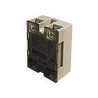
G3NA-210B-UTU DC5-24
Manufacturer Part Number
G3NA-210B-UTU DC5-24
Description
Solid State Relays SS Relay 10 A 5 to 24 VDC
Manufacturer
Omron
Datasheet
1.Y92B-A150N.pdf
(18 pages)
Specifications of G3NA-210B-UTU DC5-24
Control Voltage Range
5 VDC to 24 VDC
Load Voltage Rating
240 VAC to 240 VAC
Load Current Rating
10 A
Contact Form
1 Form A
Output Device
SSR
Mounting Style
DIN Rail
Input To Output Isolation Method
Phototriac
Relay Type
General Purpose Hockey Puck
Termination Style
Screw
Operating Voltage Range
19VAC To 264VAC
Load Current
10A
Isolation Voltage
4000VAC
Control Voltage Type
DC
Relay Terminals
Screw
Output Voltage Min
24VAC
Input Type
DC
Output Type
AC
Input Voltage (max)
32V
Output Voltage (max)
264V
Input Current (max)
7mA
Output Current
10A
Pin Count
4
Mounting
Screw
Operating Temp Range
-30C to 80C
Operating Temperature Classification
Commercial
Rad Hardened
No
Lead Free Status / RoHS Status
Lead free / RoHS Compliant
Lead Free Status / RoHS Status
Lead free / RoHS Compliant, Lead free / RoHS Compliant
Other names
G3NA210BUTUDC524NC


■ Precautions on Operating and Storage Environments
1. Operating Ambient Temperature
The rated value for the ambient operating temperature of the G3NA
is for when there is no heat build-up. For this reason, under condi-
tions where heat dissipation is not good due to poor ventilation, and
where heat may build up easily, the actual temperature of the G3NA
may exceed the rated value resulting in malfunction or burning.
When using the G3NA, design the system to allow heat dissipation
sufficient to stay below the Load Current vs. Ambient Temperature
characteristic curve. Note also that the ambient temperature of the
G3NA may increase as a result of environmental conditions (e.g., cli-
mate or air-conditioning) and operating conditions (e.g., mounting in
an airtight panel).
2. Transportation
When transporting the G3NA, observe the following points. Not doing
so may result in damage, malfunction, or deterioration of perfor-
mance characteristics.
• Do not drop the G3NA or subject it to severe vibration or shock.
• Do not transport the G3NA if it is wet.
• Do not transport the G3NA under high temperatures or humidity.
• Do not transport the G3NA without packing it properly.
1. Leakage Current
A leakage current flows through a snubber circuit in the G3NA even
when there is no power input. Therefore, always turn OFF the power
to the input or load and check that it is safe before replacing or wiring
the G3NA.
466
■ Operation
Switch element Snubber circuit
Solid State Relay
Leakage current
G3NA
3. Vibration and Shock
Do not subject the G3NA to excessive vibration or shock. Otherwise
the G3NA may malfunction and internal components may be
deformed or damaged, resulting in failure of the G3NA to operate. To
prevent the G3NA from abnormal vibration, do not install the G3NA in
locations or by means that will subject it to vibration from other
devices, such as motors.
4. Solvents
Do not allow the G3NA or the resin portion of the Fan’s thermostat to
come in contact with solvents, such as thinners or gasoline. Doing so
will dissolve the markings on the G3NA.
5. Oil
Do not allow the G3NA terminal cover to come in contact with oil.
Doing so will cause the cover to crack and become cloudy.
2. Screw Tightening Torque
Tighten the G3NA terminal screws properly. If the screws are not
tight, the G3NA will be damaged by heat generated when the power
is ON. Perform wiring using the specified tightening torque.
3. Handling Relays
Do not mount the G3NA when your hands are oily or dirty, e.g., with
metal powder. These may cause G3NA failure.
4. Do Not Drop
Be careful not to drop a Relay or Heat Sink onto any part of your
body while working. Injury may result. This is particularly true for the
High-capacity Heat Sink (Y92B-P250NF), which weighs 2.5 kg.
Related parts for G3NA-210B-UTU DC5-24
Image
Part Number
Description
Manufacturer
Datasheet
Request
R

Part Number:
Description:
RELAY SSR 10A 200-240VAC ZERO
Manufacturer:
Omron
Datasheet:

Part Number:
Description:
RELAY SSR 120VAC@10A ZERO AC IN
Manufacturer:
Omron
Datasheet:

Part Number:
Description:
SOLID STATE RELAY/TUV MARKINGS
Manufacturer:
Omron
Datasheet:
Part Number:
Description:
RELAY SSR 120VAC@10A ZERO AC IN
Manufacturer:
Omron
Datasheet:
Part Number:
Description:
SOLID STATE RELAY
Manufacturer:
Omron
Datasheet:

Part Number:
Description:
SSR, PANEL MOUNT, 264VAC, 24VDC, 10A
Manufacturer:
Omron
Datasheet:

Part Number:
Description:
SSR, 10A
Manufacturer:
Omron
Datasheet:


Part Number:
Description:
RELAY; SSR; GEN PURP; CUR-RTG 10A; CTRL-V 5-24DC; VOL-RTG 24-240AC; 4 PIN
Manufacturer:
Omron Automation
Datasheet:
Part Number:
Description:
RELAY; SSR; GEN PURP; CUR-RTG 10A; CTRL-V 100-120AC; VOL-RTG 24-240AC; 4 PIN
Manufacturer:
Omron Automation
Datasheet:
Part Number:
Description:
RELAY; SSR; GEN PURP; CUR-RTG 10A; CTRL-V 200-240AC; VOL-RTG 24-240AC; 4 PIN
Manufacturer:
Omron Automation
Datasheet:
Part Number:
Description:
G6S-2GLow Signal Relay
Manufacturer:
Omron Corporation
Datasheet:
Part Number:
Description:
Compact, Low-cost, SSR Switching 5 to 20 A
Manufacturer:
Omron Corporation
Datasheet: