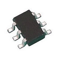
LH1522AAC Vishay, LH1522AAC Datasheet - Page 4

LH1522AAC
Manufacturer Part Number
LH1522AAC
Description
Solid State Relays Normally Open Dual Form 1A
Manufacturer
Vishay
Datasheet
1.LH1522AB.pdf
(7 pages)
Specifications of LH1522AAC
Load Voltage Rating
200 V
Load Current Rating
0.2 A
Contact Form
2 Form A
Output Device
MOSFET
Case Color
Black
Maximum Operating Temperature
+ 85 C
Minimum Operating Temperature
- 40 C
Relay Type
Solid State
Package / Case
PDIP SMD
Output Type
AC or DC
Termination Style
Solder Pad
Load Voltage Max
200V
Load Current
120mA
On State Resistance Max
15ohm
Contact Configuration
SPST-NO
Isolation Voltage
5300V
Forward Current If
1mA
Relay Terminals
SMD
Load Current Rms Max
140mA
Mounting Style
SMD/SMT
Lead Free Status / RoHS Status
Lead free / RoHS Compliant
Lead Free Status / RoHS Status
Lead free / RoHS Compliant, Lead free / RoHS Compliant
Available stocks
Company
Part Number
Manufacturer
Quantity
Price
Company:
Part Number:
LH1522AAC
Manufacturer:
SIEMENS
Quantity:
5 510
Company:
Part Number:
LH1522AAC
Manufacturer:
ICT
Quantity:
5 510
Company:
Part Number:
LH1522AAC-TR
Manufacturer:
TSC
Quantity:
12 000
Part Number:
LH1522AACTR
Manufacturer:
VISHAY/威世
Quantity:
20 000
LH1522AB, LH1522AAC, LH1522AACTR
Vishay Semiconductors
www.vishay.com
4
THE PRODUCT DESCRIBED HEREIN AND THIS DATASHEET ARE SUBJECT TO SPECIFIC DISCLAIMERS, SET FORTH AT
ilh1522ab_06
Fig. 7 - Variation in On-Resistance vs. LED Current
ilh1522ab_07
ilh1522ab_08
Fig. 8 - Switch Capacitance vs. Applied Voltage
- 0.5
0.30
0.25
0.20
0.15
0.10
0.05
1.5
1.0
0.5
80
70
60
50
40
30
20
10
0
0
0
0
0
Fig. 9 - Insertion Loss vs. Frequency
10
2
R
L
LED Forward Current (mA)
= 600 Ω
4
2
0
Applied Voltage (V)
10
Frequency (Hz)
3
4
8
0
I L = 50 mA
12
For technical questions, contact:
60
10
I
T
f = 1.0 MHz
4
F
A
= 0 mA
= 25 °C
16
80
Dual 1 Form A Solid State Relay
This datasheet is subject to change without notice.
10
20
100
5
optocoupleranswers@vishay.com
ilh1522ab_10
ilh1522ab_09
ilh1522ab_11
100
Fig. 11 - Leakage Current vs. Applied Voltage
100
80
60
40
20
3.0
2.5
2.0
1.5
1.0
0.5
90
80
70
60
50
40
30
20
10
Applied Voltage at Elevated Temperatures
0
0
0
10
0
0
2
I
T
F
50 100 150 200 250 300
50 100 150 200 250 300 350 400
Fig. 12 - Leakage Current vs.
V P = 10 V
A
R L = 50 Ω
= 0 mA
10
= 25 °C
Fig. 10 - Output Isolation
3
Load Voltage (V)
Load Voltage (V)
Frequency (Hz)
10
4
10
www.vishay.com/doc?91000
5
Document Number: 83821
10
6
85 °C
350 400
70 °C
50 °C
Rev. 1.6, 17-Mar-11
10
7


